CANopen servo drives
Communication objects (CiA301)
Network Management (NMT)
The network management (NMT) protocols provide services for network initialization, error control and device status control. NMT objects are used for executing NMT services. The NMT follows a master-slave structure and therefore requires that one CANopen device in the network fulfills the function of the NMT master. All other CANopen devices are regarded as NMT slaves. An NMT slave is uniquely identified in the network by its Node-ID, a value in the range of 1 to 127.
NMT state machine
The NMT state machine defines the communication status for CANopen devices.
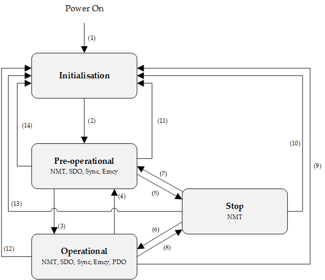
Transition | Event |
|---|---|
(1) | After power on the system goes directly to initialization state |
(2) | Once initialization is completed the system enters to Pre-operational state |
(3), (6) | Reception of Start remote node command |
(4), (7) | Reception of Enter pre-operational state command |
(5), (8) | Reception of Stop remote node command |
(9), (10), (11) | Reception of Reset node command |
(12), (13), (14) | Reception of Reset communication command |
NMT state initialization
The initialization state could be divided into three sub-states that are executed in a sequential way: Initializing (performs the basic CANopen initialization), Reset application (in where all manufacturer-specific and standardized profile area parameters are set) and Reset communication (where the communication profile and parameters are set).
At the end of initialization state the device sends a boot-up message and goes directly to Pre-Operational state.
NMT state pre-operational
In Pre-Operational state, the communication using SDO messages is possible. PDO messages are not yet defined and therefore communication using these message is not allowed. The device will pass to Operational message after receiving a NMT start node command.
Normally the master puts a node in Pre-Operational state during the set-up and configuration of device parameters.
NMT state operational
In Operational state all kind of messages are active, even PDO messages.
NMT state stopped
When entering in Stopped state, the device is forced to stop all communications with the exception of the NMT commands. (Node Guarding & Life Guarding).
NMT states and communication object relation
Following table shows the relation between communication states and communication objects. Services on the listed communication objects may only be executed if the devices involved in the communication are in the appropriate communication states
Pre-Operational | Operational | Stopped | |
|---|---|---|---|
NMT services | X | X | X |
NMT error control | X | X | X |
PDO | X | ||
SDO | X | X | |
Sync object | X | X | |
Emergency object | X | X |
NMT services
The structure of each NMT service command is as follows:
COB-ID (hex) | Number of Bytes | Data field | |
|---|---|---|---|
Byte 1 | Byte 2 | ||
000 | 2 | Command specifier | Node ID |
The possible NMT services commands are the followings:
Command specifier (hex) | Command description |
|---|---|
01 | Start remote node |
02 | Stop remote node |
80 | Enter pre-operational |
81 | Reset node |
82 | Reset communication |
Example of NMT services
COB-ID (hex) | Number of Bytes | Data (hex) | Description |
|---|---|---|---|
000 | 2 | 80 01 | NMT Host commands node 1 into Pre-Operational state |
000 | 2 | 01 01 | NMT Host commands node 1 into Operational state |
000 | 2 | 02 01 | NMT Host commands node 1 into Stopped state |
000 | 2 | 82 01 | NMT Host commands a communication reset to node 1 |
701 | 1 | 00 | Node 1 response with a boot-up message |
NMT error control
Summit devices support Node guarding, life guarding, and heartbeat protocols. These protocols are used to detect network errors on both sides (master and drive), the code reported by this error is 0x00008130, and the reaction can be configurable through the Abort Connection option code and Error behavior.
Note
Heartbeat and node/life guarding cannot be activated both at the same time.
Node guarding service
The NMT Master can monitor the communication status of each node using the Node Guarding protocol.
During node guarding, a controller is polled periodically and is expected to respond with its communication state within a pre-defined time frame. Note that responses indicating an acceptable state will alternate between two different values due to a toggle bit in the returned value. If there is no response, or an unacceptable state occurs, the NMT master could report an error to its host application.
The NMT master sends a node guarding request using the following a Remote Frame message:
COB-ID (hex) | Number of Bytes | RTR |
|---|---|---|
700 + Node ID | 0 | 1 |
The NMT slave will generate a node guarding answer using the following message:
COB-ID (hex) | Number of Bytes | RTR | Data field (Byte 1) | |
|---|---|---|---|---|
Bit 7 | Bit 6 to 0 | |||
700 + Node ID | 1 | 0 | Toggle | NMT communication state |
Note that the slave answers toggling a bit between consecutive responses. The value of the toggle bit of the first response after the guarding protocol becomes active is zero.
The state of the heartbeat producer could be one of the followings:
Communication State value (hex) | State definition |
|---|---|
00 | Boot-up |
04 | Stopped |
05 | Operational |
7F | Pre-operational |
Example of NMT Node guarding
COB-ID (hex) | Number of Bytes | RTR | Data field (hex) | Description |
|---|---|---|---|---|
701 | 0 | 1 | - | Master sends a CAN remote frame without data to node 1. |
701 | 1 | 0 | 7F | Node 1 sends the actual NMT state (pre-operational) toggling the 7th bit. |
701 | 0 | 1 | - | Master sends a CAN remote frame without data to node 1. |
701 | 1 | 0 | FF | Node 1 sends the actual NMT state (pre-operational) toggling the 7th bit. |
Life guarding service
In Life guarding protocol, the NMT slave monitors the status of the NMT master. This protocol utilizes the objects Guard time (0x100C) and Life time factor (0x100D) to determine a "Lifetime" for each NMT slave (Lifetime = Guard Time * Life Time Factor). If a node does not receive a Node Guard message within its Lifetime, the node assumes communication with the host is lost sends an emergency message, performs a fault reaction, and enables the ERR LED signal. Each node may have a different Lifetime.
Example of NMT life guarding
COB-ID (hex) | Number of Bytes | RTR | Data field (hex) | Description |
|---|---|---|---|---|
701 | 0 | 1 | - | Master sends a CAN remote frame without data to node 1 |
701 | 0 | 1 | - | Master sends a CAN remote frame without data to node 1 |
… | … | … | … | Delay Higher than Guard Time * Life Time Factor |
81 | 8 | 0 | 30 81 11 00 00 00 00 00 | Node 1 send an EMCY indicating the lifeguard error |
Note
To start the Life Guarding protocol, both Guard Time and Life Time Factor need to be different than 0, and a first CAN remote frame without data needs to be sent to each node.
Do not use the life guarding service
It is recommended to use the heartbeat service instead of using the life guarding service to confirm that the node is still available.
Heartbeat service
The heartbeat protocol defines an error control service without the need for a remote frame. A heartbeat producer transmits a Heartbeat message cyclically. Transmit cycle of heartbeat message could be configured using the object Producer heartbeat time (0x1017). If the Heartbeat is not received by the consumer within an expected time, specified by the Consumer heartbeat time (0x1016), it could report an error to its host application. Summit devices can work as heartbeat producers or consumers.
The heartbeat message generated by the producer will be as follows:
COB-ID (hex) | Number of Bytes | Data field (Byte 1) | |
|---|---|---|---|
Bit 7 | Bit 6 to 0 | ||
700 + Node ID | 1 | Reserved | NMT communication state |
The state of the heartbeat producer could be one of the followings:
Communication State value (hexadecimal) | State definition |
|---|---|
00 | Boot-up |
04 | Stopped |
05 | Operational |
7F | Pre-operational |
Example of NMT heartbeat producer
COB-ID (hex) | Number of Bytes | Data field (hex) | Description |
|---|---|---|---|
705 | 1 | 7F | Node 5 sends a heartbeat indicating pre-operational state. |
705 | 1 | 7F | After producer heartbeat time, Node 5 sends again a heartbeat indicating pre-operational state. |
Example of NMT heartbeat consumer
COB-ID (hex) | Number of Bytes | Data field (hex) | Data field | Description |
|---|---|---|---|---|
701 | 1 | 05 | - | Master (node 1) sends a CAN heartbeat indicating operational state |
701 | 1 | 05 | - | Master (node 1) sends a CAN heartbeat indicating operational state |
| ... | ... | ... | ... | Delay Higher than heartbeat consumer time |
85 | 8 | 0 | 30 81 11 00 00 00 00 00 | Node 5 (heartbeat consumer device) sends an EMCY indicating the heartbeat error |
Boot-up service
An NMT slave issues the Boot-up message to indicate to the NMT-Master that it has entered the state Pre-operational from state Initialising.
Example of NMT Boot-up
COB-ID (hex) | Number of Bytes | Data field (hex) | Description |
|---|---|---|---|
701 | 1 | 00 | Node 1 sends a boot-up NMT message |
Layer Setting Services (LSS)
LSS service is available from the master with COB-ID 2021 (0x7E5), this service allow to identify and configure CANopen devices without knowing the Node-Id. The device will answer the master's transmissions at COB-ID 2020 (0x7E4). LSS allow to configure device Node-ID and baudrate.
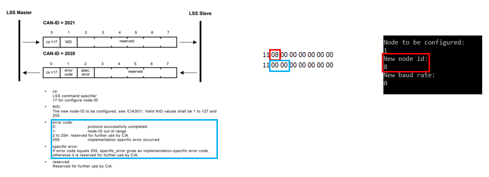
Node-id modification protocol
Previous requirement is to set the desired device on the net to Selective configuration state.
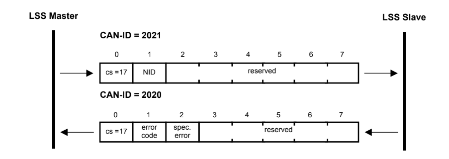
To modify the Node-ID, the master may send a message with command '17', indicating the Node-ID that the device must take.
- NID: Node-ID to apply to the device.
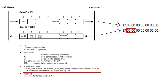
- Error code:
0: Node-ID configured successfully.
1: Node-ID out of range. - Specific error: reserved for future uses.
After Node-ID is configured, it is necessary to make a communication reset of the node to apply the new Node-ID to the communication objects.
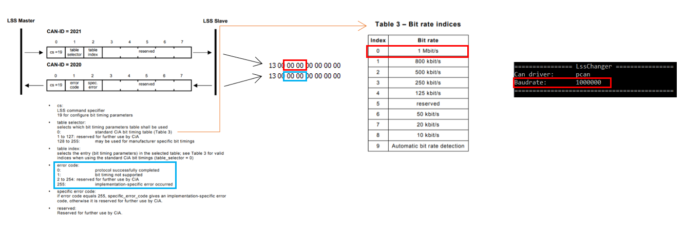
Bit-timing modification protocol
Previous requirement is to set the desired device on the net to Selective configuration state.
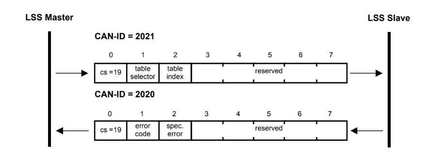
To modify the bit-timing, the master may send a message with command '19', indicating the new baudrate that the device must take. Bit timing must be selected by using the table + index identification.
- Table selector:
0: CiA bit timing table
1 - 255: reserved for future use - Table index:
0: 1Mbps.
1: 800Kbps (not supported).
2: 500Kbps.
3: 250Kbps.
4: 125Kbps.
5: 50Kbps.
6: 20Kbps.
7: 10Kbps. - Error code: reserved for future uses.
0: Bit-timing configured successfully.
1: Bit-timing not supported. - Specific error: reserved for future uses.
After bit-timing is configured, it is necessary to send a bit-timing activation message.
Example of LSS
In this example, we will change from the initial node 15, to node 8. As it can be seen on the following image, only one device is detected, which has been connected with a PCAN driver.
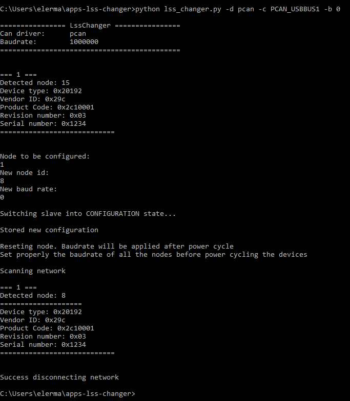
By PCAN-view software, the following sequence has been recorded when changing from one node to another. LSS messages transmitted by the LSS master device shall use the CAN-ID 2021d (0x7E5). LSS messages transmitted
by the LSS slave device(s) shall use the CAN-ID 2020d (0x7E4). Comment that data is transferred in litte-endian, this means, the order of the bytes of a data are swapped.
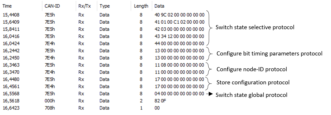
Apart from that, the last two lines corresponds to a NMT reset node and a boot-up message respectively.
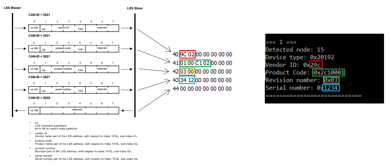
Switch state selective protocol
By the following five lines, the drive connected is analyzed. Such as, vendor ID, product code, revision number or serial number.
Configure bit timing parameters protocol
On the following two lines, the baudrate is configured. In this case, baudrate has not been changed, so the initial and final baudrate are the same.
Configure node-ID protocol
The protocol defined here is used to implement the configuration of the node_ID service.
Store configuration protocol
The following two lines are the ones in charge to store the new configuration.
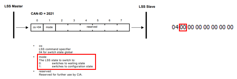
Switch state global protocol
Finally, state is switches to a waiting state.
EMCY service
The EMCY service is an asynchronous producer-consumer protocol on which the producer indicates that an error has been detected by sending an EMCY message. The consumer can easily know the error source that has been detected by the node at the error instant without polling the statusword or the error register.
Each produced EMCY message is reflected in register 0x1001. The EMCY message can both indicate that an error has been produced and also that an error condition has been removed (error code "no error"). Each error indicates the code of the error, and also the affected module.
An emergency object is sent only once per error event.
The reaction on the received EMCY messages is application-specific. By default the EMCY message CAN ID is "0x80 + Node ID". The COB-ID can be modified by means of SDO service through the register 0x1014.
The data content of the emergency message uses the following structure:
| COB-ID (hex) | Byte number: | 1 | 2 | 3 | 4 | 5 | 6 | 7 | 8 |
|---|---|---|---|---|---|---|---|---|---|
| 080 + Node ID | Emergency error code | Error register (Object 0x1001) | Subnode | Reserved (zero values) | |||||
Example of EMCY
COB-ID (hex) | Number of Bytes | Data field (hex) | Description |
|---|---|---|---|
89 | 8 | 72 73 21 01 00 00 00 00 | Drive in node 9 sends an emergency message indicating a digital encoder runaway error (0x7372) in the subnode 1. Register 0x1001 = 0x21 indicates the active error with the corresponding bits set to 1. |
89 | 8 | 00 00 00 00 00 00 00 00 | Drive in node 9 indicates that the error condition has been removed (errorcode = 0x0000). Register 0x1001 = 0 indicates that there are no active errors. This EMCY message has been sent in the fault reset event. |
Refer to Error management section for the error code description list.
Everest products only
Linking faults with EMCY service (Everest products only)
Faults can be linked to EMCY service by means of register error notification source. Further information can be found in Error management section.
Process data object (PDO)
PDOs are messages send without confirmation used for real time information transfer. PDOs are mapped to a single CAN frame and can contain multiple object dictionary entries with a maximum of 8 bytes of data. Each PDO has an identifier and is transmitted by only one node in the network, however it could be received by more than one node. PDOs must be configured previous to using them.
There are two types of PDO messages: Transmit PDO (TPDO) and Receive PDO (RPDO).
The trigger event of the PDO message could be configured using the communication parameter object and the object dictionary entries transmitted could be also defined using the PDO mapping list.
Therefore, each PDO is defined by means of:
- A PDO communication parameter
- A PDO mapping object
Summit drives include 4 RPDO and 4 TPDO.
Transmit PDO (TPDO)
TPDOs are configured to send data from node to master after the occurrence of a trigger event or after a remote request by means of a RTR.
TPDOs have three transmission types:
- Internal event or timer: Message transmission is triggered when the value mapped into the PDO has changed or when the specified time (event-timer) has elapsed. PDO transmission is controlled by producer.
- Remotely request: Message transmission is initiated on receipt of a RTR message. PDO transmission is driven by the PDO consumer.
- Synchronously trigger: Message transmission is triggered by the reception of a certain number of SYNC objects (see TPDO1 definition for further information). The PDO transmission is controlled by the SYNC producer.
Example
Example of an internal event TPDO:
COB-ID (hex) | Number of Bytes | Data field (hex) | Description |
|---|---|---|---|
182 | 2 | 63 22 | Node ID 2 sends the Transmit PDO1 with a content value of 0x2263. |
Receive PDO (RPDO)
The master uses the RPDO to write data to objects in the nodes.
RPDOs have two transmission types:
- Asynchronous: Message content is applied upon receipt of the RPDO. The PDO reception is controlled by the PDO producer.
- Synchronously trigger: Message content is applied after the reception of a certain number of SYNC objects. The PDO reception is controlled by the SYNC producer.
Example
Example of an asynchronous RPDO:
COB-ID (hex) | Number of Bytes | Data field (hex) | Description |
|---|---|---|---|
202 | 2 | 22 12 | Master sends a RPDO1 to Node 2 with a content value of 0x1222. |
Mapping procedure
The steps to configure the PDO mapping are (Example for setting the RPDO 1):
- Place the controller into NMT pre-operational.
- Destroy the PDO writing a 1 into the valid bit of SubIndex 0x01 of PDO communication parameter. (0x1400 RPDO1 - bit 31 of COB-ID used)
- Unmap all registers from PDO by setting SubIndex 0x00 to zero. (0x1600 RPDO1 mapping parameter).
- Modify mapping by changing the values in the corresponding SubIndexes. (0x1600 RPDO1 mapping parameter).
- Enable mapping by setting SubIndex 0x00 to the number of mapped objects. (0x1600 RPDO1 mapping parameter).
- Define the configuration of the PDO (transmission type, inhibit time, etc. ).
- Create PDO by setting a 0 into the valid bit of SubIndex 0x01 of PDO communication parameter. (0x1400 RPDO1 - bit 31 of COB-ID used)
- Place the controller into NMT operational.
Default PDO mapping
Summit drives implement the following default PDO mapping:
| PDO | Map 1 | Map 2 | Map 3 | Map 4 | Map 5 | Map 6 | Map 7 | Map 8 |
|---|---|---|---|---|---|---|---|---|
| RPDO 1 | 0x6040 | - | - | - | - | - | - | - |
| RPDO 2 | 0x6040 | 0x6060 | - | - | - | - | - | - |
| RPDO 3 | 0x6040 | 0x607A | - | - | - | - | - | - |
| RPDO 4 | 0x6040 | 0x60FF | - | - | - | - | - | - |
| TPDO 1 | 0x6041 | - | - | - | - | - | - | - |
| TPDO 2 | 0x6041 | 0x6061 | - | - | - | - | - | - |
| TPDO 3 | 0x6041 | 0x6064 | - | - | - | - | - | - |
| TPDO 4 | 0x6041 | 0x606C | - | - | - | - | - | - |
Storing an user-defined mapping
The drive includes 4 PDO mapping on each direction, with a pre-defined mapping configuration. These PDOs can be modified by the user (see mapping procedure) and stored in the NVM memory. The store of this configuration can be done by using register 0x1010 (store parameters).
To recover the default configuration, it can be done using register 0x1011 (Restore default parameters).
In addition, all the PDO related configuration (including mapping and COB-ID) will be recovered to their defaults if the node-ID of the device is modified (using LSS).
If node-ID is modified, PDO configuration will be restored to defaults.