Drive protections
Summit servo drives include a wide set of hardware and firmware protections that allows reaching the maximum performance with the required safety for the application and the drive itself. These protections are detailed in the product manual.
Voltage protections
Summit servo drives have been designed to operate in a wide range of voltages. Protections are available to protect the drive in front an undesired out of range reading:
Fault generation (motor stopped) if bus voltage is not correctly charged when enabling the motor.
After reaching Switched On state or higher, the drive will wait up to 5 seconds for the bus voltage to charge. Then, a fault will be generated if it's not correctly charged (not stable or below the under-voltage level).
Fault generation (motor stopped) if and under-voltage or over-voltage is detected (product limits).
Read the product manual for further details about the voltage input range.
Related registers:
Under voltage level
Over voltage level
User-configurable under and over-voltage threshold to generate the desired fault reaction. This threshold should never overcome the product limits.
If the user-configuration overcomes the drive limits, then it is ignored and only the drive protection is active.
Related registers:
User under voltage level
User over voltage level
Voltage values read by the drive are available to the user to help analyze the system in register Bus voltage value.
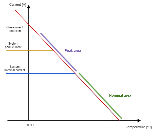
Current limit protections
Summit servo drives have current limit protections to avoid damage on the system, the actuator or the drive itself.
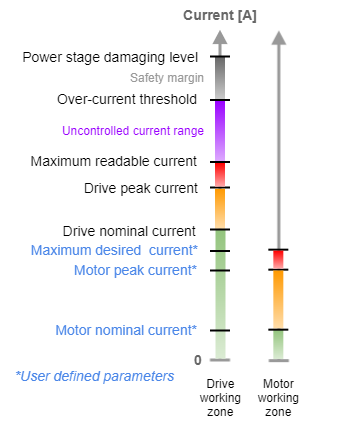
All the current threshold levels in the system can be shown in the schema, and they are basic for understanding the current protections.
The motor working zone is typically below the drive working zone, but this is user-defined. It can be adjusted as desired for the application.
The level of maximum readable current defines the absolute maximum working zone for an application, because higher currents will not be measured and therefore current will not be controlled.
Each one of those levels is related somehow to a certain current protection and may have a related register, according to the following table.
Current level | Protection name | Corresponding register |
|---|---|---|
Motor nominal current | user / motor I2T | rated current |
Motor peak current | user / motor I2T | peak current |
Maximum desired current | Maximum current limit | max. current |
Drive nominal current | system / drive I2T | maximum drive current |
Drive peak current | system / drive I2T | maximum drive peak current |
Maximum readable current | Current out of range detection | current measuring range (1 to n) |
Over-current threshold | Over-current detection | None |
Additionally, there are other protections. All the protections are listed and detailed below.
Over-current detection
This protection generates a fault condition if the drive detects a current level above the over-current threshold.
This protection is always enabled.
The over-current threshold is product dependent. The over-current threshold is checked on every drive phase and it is a hardware protection.
Current out of range detection
This protection generates a fault condition if the measured current is out of the measurable range.
This protection is enabled for some products and some firmware versions.
Related registers are the current measuring range (1 to n).
This protection offers additional level protection for those products that support multiple current measurement ranges. The over-current threshold is detected at the maximum drive capabilities, which doesn't offer good protection when the product is working in a smaller current range. See the next picture as an example:
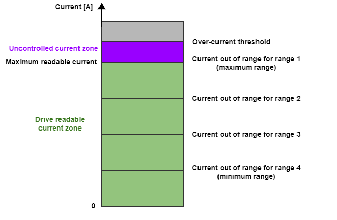
If the drive works with the minimum range current, it is far from the absolute limit area. So this protection will avoid entering this absolute limit area by generated a fault if the current measurement is out of the actual range.
Maximum current limit
This protection limits current set-points injected to the current control loops above the max current level. Further information is available on Current modes (CSC,C, CA) section.
This protection is active if at least the current loop is enabled. Therefore it is inactive in voltage mode.
Max current limit is applied to the total motor current →
I2T protection
This protection limits the current set-points to the current control loops by a thermal estimation based on current readings. The main functionality of the I2T is to detect an instantaneous exceed of thermal energy on the drive. It covers the case where the temperature sensors are too slow to detect a dangerous situation.
Background
The instantaneous energy dissipated by a motor is proportional to the square of the current circulating through it and to the time this current lasts circulating through it. The nominal current is the current that a motor can stand in a continuous manner without exceeding its thermal limits. Therefore, any current above the nominal one creates an accumulation of thermal energy in the motor's surroundings that the cooling systems will have to dissipate. If this process of accumulating thermal energy exceeds the cooling system's ability to dissipate it, the system is bound to reach its thermal limits, and permanent damage to the motor or the surrounding element can be inflicted. The so-called I2T is an indirect magnitude proportional to the energy dissipated by the motor, and the I2T protection is a control mechanism aimed to ensure that the integral of the power dissipated by the motor in the form of thermal energy does not exceed its thermal limits.
The energy dissipated by a motor is defined as:
Where is the current flowing through the motor and R is its resistance.
The current used by this algorithm is the total motor current →
The nominal current that can flow through the motor is determined by the power it can dissipate continuously without exceeding its thermal limits.
In a transient peak, the motor could tolerate an excess of energy with respect to the continuous limit.
The excess of energy could be expressed as follows:
Most times we do know the current rating system, the peak current and the maximum duration of the peak. Therefore, the equation could be simplified as follows:
This excess of energy is called I-squared-t (), and it is expressed in amper2 per second.
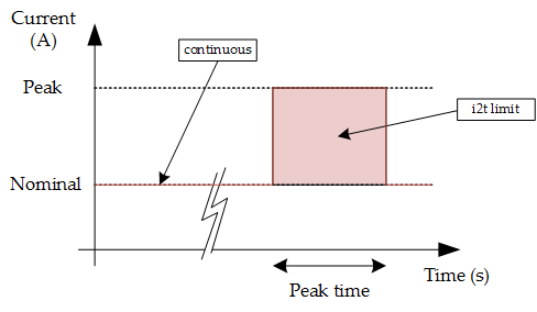
Algorithm
The following picture shows a graphical representation of the limit algorithm implemented in the controller. On the left side of the graph, the system is working with its nominal current. Under this situation, the system could be working infinitely. Once the actual current crosses the nominal current, the algorithm starts to integrate the excess of energy (red zone). If the excess of energy reaches the prefixed value, the current will be decreased to its nominal value.
Once the protection has started to limit the current, it will not allow new current peaks (greater than nominal value) until the accumulated goes to 0 (fully discharged).
There are 2 different I2T protections, which are always active simultaneously:
User/motor I2T
System/drive I2T
The system I2T always generates a fault if it is reached, for protecting the drive. In the other hand, the user I2T acts limiting the current when is activated.
System I2T values are fixed and product dependent, whereas the user I2T parameters are modifiable at any time.
I2T protection is always active. For modes of operation where the current loop is not enabled, instead of limiting the current, a fault is generated.
If system I2T is detected before the user I2T, a fault is generated independently if the current loop is enabled or not.
Related registers:
System I2T:
Maximum drive current
Maximum drive peak current
Maximum drive peak current time
User I2T:
Rated current
Peak current
Peak current time
It's important to remember that: peak current > rated current.
Register current loop status contains bits to easily check if the I2T algorithm (user I2T) is limiting.
Example of I2T
For example, if the I2T protection is configured with the following parameters:
The i2t variable or energy excess will have the following maximum value:
It means that the system will tolerate a peak of 2 A during 1 s, but also some other combinations, like for example:
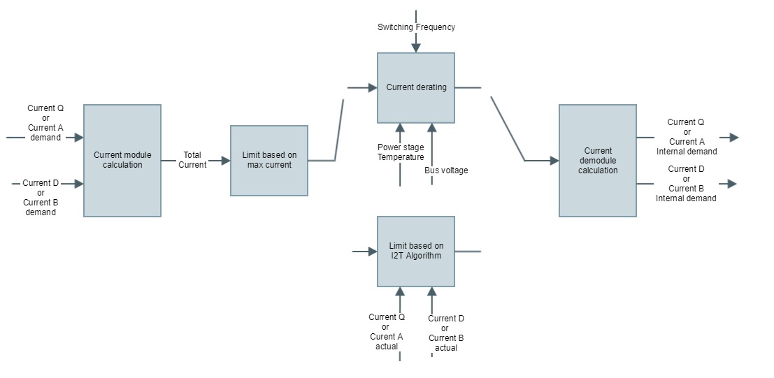
Current derating
The current limit protections for the drive itself (detailed above) are also based on the power stage temperature.
The complete current limit chain is the following one:
The derating is applied following the next equation:
and
are dependent on the selected power stage operation frequency.
is the theoretical current value supported at temperature 0.
The drive computes continuously the theoretical current derating curve point and it is compared against the output of the current limitation chain (After max current and I2T are applied). The minimum between both values is the output commanded to the current loop.
Constants ,
and
are parameters product dependent.
Register current loop status contains bits to easily check if the derating algorithm is limiting.
Temperature protections
Temperature is one of the key elements that must be monitored in order to reach the maximum performance of the drive safely. Summit servo drives are composed of multiple temperature sensors of two types:
Power stage sensors
Motor sensors
The power stage sensors are defined and parameterized by Ingenia whereas motor temperature sensor configuration is user-dependent.
Further information about motor temperature sensor options is available on the Motor and brake section.
Temperature readings of all the available sensors onboard are available for the user to monitor the state of the drive. Under and over temperature protections (both manufacturer and user limits) are based on the maximum temperature measured by all the available sensors.
Related registers are:
Power stage temperature N value (N being the number of the sensor)
Power stage max. actual temperature (maximum temperature measured by all the available sensors)
“Feedback Runaway” feature
“Feedback runaway” is a protection feature in Ingenia/Novanta motion drives that detects when an encoder (position feedback device) is behaving abnormally compared to the motor’s digital halls.
More precisely, a feedback runaway error occurs when:
The drive compares the selected encoder feedback against the digital halls on each mechanical revolution.
If the detected feedback counts per revolution differ by more than 20% from the specified feedback resolution, the drive triggers a feedback runaway error.
This is used to catch issues like a faulty/disconnecting encoder or an encoder rotor slipping on the shaft, so that the drive can stop or react safely (e.g., disable power stage, slow down motion).
So, “feedback runaway” means the encoder feedback is “running away” from what the halls indicate the motor is really doing, beyond an allowed 20% discrepancy, and the drive flags this as an error for safety.
“Feedback runaway” limitations
Current Feedback runaway limitations include:
It cannot detect a runaway event before a full mechanical revolution.
The error threshold is fixed at 20%.
It cannot detect malfunctioning in the digital halls
Alternatives to detecting the feedback runaway before 1 mechanical cycle
Integrity check 1: checks that the difference between the commutation angle determined by the commutation sensor and the halls feedback remains below a threshold. If the difference exceeds this threshold, a fault triggers. The difference is calculated at each hall transition event, enabling fault detection in the commutation sensor within one or two hall transitions.
Integrity check 2: it accumulates the readings of the commutation sensor in each loop cycle; then the accumulator is reset on each hall transition. If hall transitions are lost, the accumulator variable will surpass a certain threshold, so a fault is triggered reporting a hall malfunction.
Integrity check 1 and Integrity check 2 complement each other. Integrity check 1 may not trigger when hall transitions are lost; in this case, Integrity check 2 operates effectively. Conversely, Integrity check 2 cannot detect if the accumulator fails to increase due to a commutation sensor malfunction; here, Integrity check 1 triggers.
Angle Integrity Check 1
Angle Integrity Check 1, uses the digital hall sensor as a reference to detect a drift or misalignment of the commutation sensor. It can detect motor runaway conditions within 1 electrical cycle.
At each digital hall transition, the drive latches the electrical angle from the commutation sensor, and the electrical angle from the digital halls (this will include any hall sensor compensation that has been implemented).


From the first transition it stores a calibration angle difference between both sensors. On every subsequent transition, it recomputes this angle difference and compares it against the calibration value to measure sensor drift. If the absolute drift exceeds a user‑configurable Angle integrity check 1 threshold, the drive declares an angle integrity fault.

This check assumes:
Motor pole pairs are correctly configured
The correct commutation sensor is selected and configured
Digital halls are enabled and active as feedback
The user sets a tolerance for this deviation. Exceeding it triggers a runaway error.
Registers used:
0x2394 - Feedback runaway source - Indicates the feedback checked against digital halls
0x0160 - Angle integrity check 1 threshold - Indicates the tolerable angle deviation between the selected commutation feedback and the digital halls
0x061E - Angle integrity check 1 error option code - Sets the drives fault reaction to the angle integrity check
Angle integrity check 2
The angle integrity check 2 is a complimentary algorithm to ensure that the angle integrity check 1 is working correctly. The main aim of the angle integrity check 2 is to detect if the digital hall transitions are being missed. Missing digital hall transitions could cause the angle integrity check 1 to miss the detection of a commutation sensor angle drift. This check would also help identify a malfunctioning hall sensor, although it already counts with some error detection mechanisms by itself (hall sequence error and hall transition error).
How does the angle integrity check 2 work?
Commutation angle accumulator
On every position/velocity loop update, the device integrates the commutation angle deltas between each control loop cycle using an accumulator variable. These commutation angle deltas are calculated in the following way:
Where is the commutation sensor angle difference between the latest sample and the previous one. The commutation angle accumulator works in the following way:
Where increments with every loop iteration.
Commutation angle accumulator clear
On every digital hall transition, is set to 0. On an ideal system where digital hall transitions are triggered with perfect timing,
should never exceed 60º, and should always be reset to 0º then. In reality, the commutation angle accumulator might be cleared slightly before or after the 60º value, but never too far off.
Error detection
The angle integrity check 2 triggers an error when the commutation angle accumulator exceeds a certain threshold. Given that the digital hall transitions happen at roughly 60 electrical degrees, and that these transitions clear the commutation angle accumulator used in this algorithm, the threshold should be set somewhere between 60º and 120º in order to detect a digital hall transition loss.
This threshold is given by the Angle integrity check 2 threshold parameter.
Note
The Angle integrity check 2 threshold is expressed in unitary values (0.0 equals 0 electrical degrees, 1.0 equals 360 electrical degrees). As stated above, the threshold should be set somewhere between 60º and 120º in order to detect a digital hall transition loss, so the usable angle integrity check 2 threshold values range from 0.1666 to 0.3333.
Example

Requirements
The requirements for this check to work properly are:
Having the motor pole pairs correctly configured
Having the correct commutation sensor selected and configured
Having digital halls sensor active (normally as reference sensor, but position, velocity or auxiliar sensor also works)
Is the angle integrity check 2 error persistent?
This error can be cleared. If the error persists in the system (hall transitions are not being triggered), the error will be triggered again after a 60-120 electrical degree motion if the angle integrity check 2 threshold is configured in this range.
What could be triggering angle integrity check 2?
This check could be triggered by any of the following reasons:
Commutation sensor malfunction
Digital hall sensor disconnection
Digital hall sensor malfunction
Incorrect motor pole pairs
Using the internal generator as commutation sensor. When using the internal generator as commutation sensor, angle ramps are generated by the device and they do not represent the real motion of the motor. This can trick the algorithm and trigger a false positive. When using the internal generator as commutation sensor, make sure the angle integrity check 2 threshold is set to a very high value or that digital halls are de-selected from all feedbacks.
Setting the Angle integrity check 2 threshold to small enough value. Setting this threshold below the minimum angle that the digital hall transitions can cover will result in an error. Also, system imperfections, may require this threshold to be slightly higher than its ideal value.
Digital hall filter too aggressive. The glitch filters implemented in this feedback could be configured to very aggressive cutoff frequencies, causing a loss of transitions.
Configuration parameters
How to disable this check
Set a high value (above 1.0) in the angle integrity check 1 threshold parameter
De-select the digital halls from any feedback sensors.
How does commutation sensor alignment affect the angle integrity checks
The commutation sensor alignment procedure does not affect the angle integrity checks. This is because the integrity checks only require information about the deviation of the angle readings between the feedback to be checked and the reference feedback (digital halls). The offset against the driver's coordinates is not important in this case.
Safe torque off (STO)
The Safe Torque Off (STO) is a drive-integrated safety function that ensures no torque-generating energy can be applied to the motor. The status of this circuit can be monitored by the user via the STO status reporting parameter.
Info
To activate or deactivate the STO, both inputs STO1 and STO2 need to be set to the same value. It is product dependent whether both to a low level or both to a high level will disable the power stage