Torque modes (CST, T)
Torque mode is used to command the torque that the actuator applies. It requires a proper configuration of the commutation sensor.
The commutation sensor configuration process is described in the Commutation section.
If software position limits are enabled using this mode of operation, the drive will generate a fault if the position limits are exceeded. Set them to 0 to disable this functionality.
If actuator velocity overcomes the max. velocity parameter using this mode of operation, the drive will generate a fault. See Error Management section for more information.
Torque loop availability depends on the product and firmware version.
With torque loop
Control scheme
The implemented PI module follows the next block diagram:
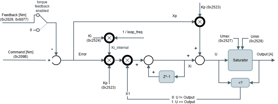
The output of the control loop at the kth sample is:
Where:
U is the output before entering in the saturator, in [A].
The output after the saturator is limited to the values Umax and Umin, so if the output signal is outside these parameters, the output is clamped.
Command c is the Command signal (Output of the Reference + Filters + offset), in [Nm].
Feedback f is the Filtered Feedback signal (Output of the Feedback + Filters), in [Nm].
Kp & Ki are the PI gains. Kp in [A/Nm] and Ki in [Hz].
Ki_internal is non-dimensional.xp is the proportional path:
We don't have a way to export this inline extension.xi is the integral path:
where x1 is:We don't have a way to export this inline extension.
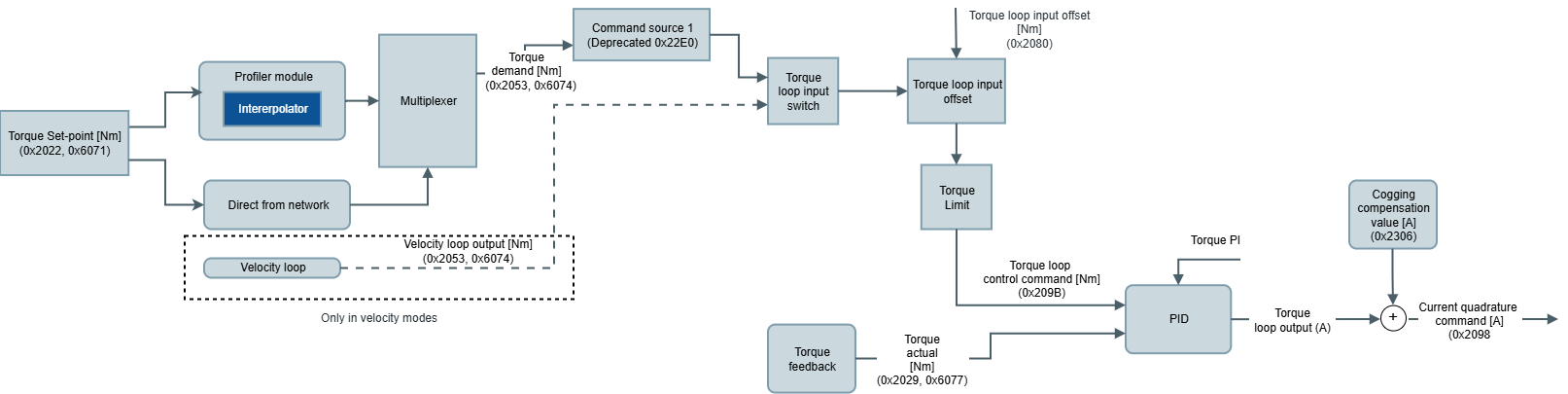
The output of the torque controller is connected to the current quadrature command (before the filters and offset) of the current control. The current direct command is set to 0 A.
All torque modes work with a PI controller and its parameters are:
0x2523 - Torque loop Kp (Kp).
0x2524 - Torque loop Ki (Ki).
0x2527 - Torque loop max. output (Umax).
0x2528 - Torque loop min. output (Umin).
0x2053 - Torque demand/0x6074 - Torque demand is the reference input of the PI.
0x209B - Torque loop control command is the command value after offset is applied (Command signal from the diagram).
0x21E4 - Torque control loop error is the difference between the reference and feedback values in the control loop (Control loop error signal from the diagram).
0x2029 - Actual torque/0x6077 - Torque actual value is the torque value read by the feedback.
0x2022 - Torque set-point, 0x6071 - Target torque is the target commanded to the torque modes of operation.
On the other hand, the implemented controller supports additional features:
Torque feedback enabled allows opening the loop of the PI. It is configured with register 0x2510 - Control loops feedback options. The feedback path is removed from the real feedback signal and it forces a value of 0.
0x2520 - Position & velocity loop rate contains also the update rate of execution of the torque PI.
Torque Offset
In some applications, the PI is not enough for proper control. In these cases, there is an additional input through the reference signal to the PI that is identified as Offset in the diagram. The purpose of this 0x2080 - Torque loop input offset/0x60B2 - Torque offset is to be used by an external master to compensate for the system dynamics based on information that cannot be read directly by the drive.
Torque feedbacks
Current implementation limitations
Currently, the only torque feedback available is a torque estimator based on the read quadrature current.
Torque estimator based on read quadrature current.
Related registers:0x243B - Torque constant: Conversion factor for the torque estimator to read torque from quadrature current values.
In the current implementation, Torque feedback enabled is set to disabled, so the torque constant is only for visualization and does not affect to the loop.
Torque loop Kp acts as the torque constant, is set to 1.0 by default so the torque loop has no effect in the other modes of operation.
Torque loop Ki has to be 0.0 so it has no effect.
Torque mode (T)
Torque (T) mode uses the above control scheme, connecting the torque set-point input from the application directly to the Torque demand signal mentioned above.
Note
Set-points will begin being taken into account after transitioning to the "operation enabled" state on the drive.
Cyclic Synchronous Torque (CST)
Cyclic Synchronous Torque mode (CST) uses the above control scheme as well but connects the torque demand to the linear profile of the set-point manager.
Note
The linear profile starts immediately upon a change of torque set-point.
Warning
It is mandatory to configure the 0x21EF - Interpolation time mantissa and 0x21F0 - Interpolation time exponent. The value of these parameters will determine how the linear profile will be performed. The product of these two parameters should match the time that will take to update the current quadrature set-point. More information about the linear profile can be found in the Set-point manager and interpolator buffer section.
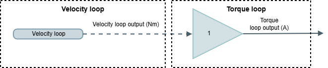
Without torque loop (legacy)
Control scheme
Torque estimation is based on current measurements. Velocity control loop is directly connected to current control loop. Therefore the current control scheme is the same as the used on Current modes. A current limit block is available to protect the system in front of high commanded currents or the excessive amount of energy accumulated (I2T).
This mode of operation connects current direct set-point and current quadrature set-point inputs to the interpolator from the set-point manager. The interpolator will begin to generate current direct demand and current quadrature demand after a change in any of the previous signals.
The Cyclic Synchronous Torque mode is obtained keeping current direct set-point to 0 A and using current quadrature set-point as a single set-point. From the user point of view the involved registers are:
Torque constant defines the relationship of the magnitude current quadrature (A) and torque (N).
Target torque is linked to the current quadrature set-point. The units are thousands of rated torque.
Torque actual value is the representation of current quadrature value in thousands of rated torque units.
Torque offset value is linked to the current quadrature loop input offset. The units are thousands of rated torque.
The PI parameters involved are the same as the used in current modes based on direct and quadrature components.
Cyclic Synchronous Torque (CST) mode
Note
The linear profile starts immediately upon a change of torque set-point.
Warning
It is mandatory to configure the interpolation time mantissa and interpolation time exponent. The value of these parameters will determine how the linear profile will be performed. The product of these two parameters should match the time that will take to update the current quadrature set-point. More information about the linear profile can be found in the Set-point manager and interpolator buffer section.
Cogging compensation
The cogging compensation is injected in the torque loop output as a feedforward.
Explanation of cogging compensation can be found in the following page: Cogging compensation