Signalling LEDs
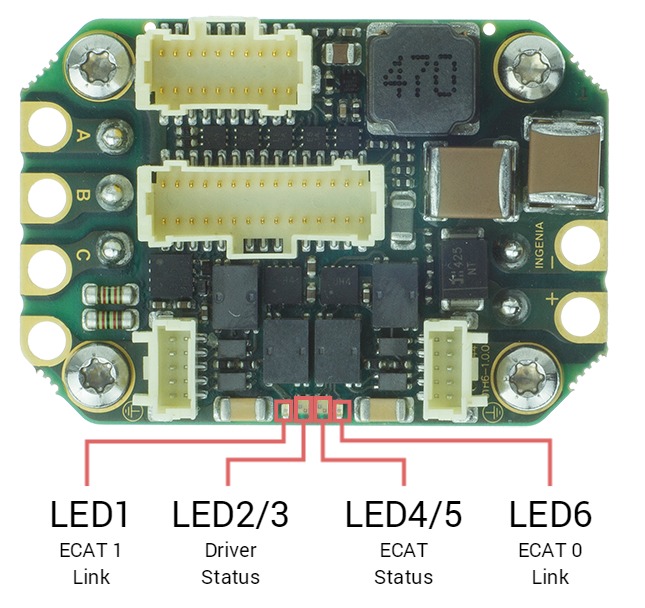
The drive provides information through 6 signalling LEDs:
| LED | Type | Color | Description |
|---|---|---|---|
| LED6 | Single | Green | EtherCAT / Ethernet 0 link (ECAT 0 Link or LINK0) |
| LED1 | Single | Green | EtherCAT / Ethernet 1 link (ECAT 1 Link or LINK1) |
| LED2/3 | Bi-color | Green / Red | Driver Status. Two LEDs indicate the driver status.
|
| LED4/5 | Bi-color | Green / Red | EtherCAT / CANopen Status (ECAT Status). Two LEDs indicate the EtherCAT or CANopen status.
|
The meaning of the signaling depends on the product variant, see LED signals reference for details.
LEDs at start-up & Troubleshooting
After powering on, some of the LED signals can help troubleshoot.
EtherCAT
LED signal | Expected start-up behavior |
|---|---|
LINK0 and LINK1 (Green) | ON-OFF alternating → The port is open and ready for activity. If EtherCAT cables are connected on ECAT Port 0/1, Link LEDs will light according to the definition. EtherCAT firmware starts with no other LED because the slave will stay in INIT State after power-up until an EtherCAT master forces it to transition to another state. |
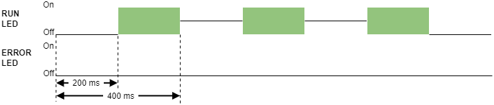
RUN LED (Green) | OFF → The slave will stay in INIT State after power-up until an EtherCAT master forces it to transition to another state. |
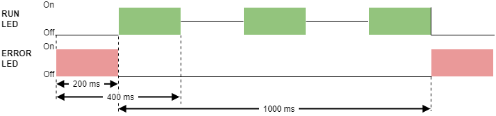
ERROR LED (Red) | OFF → The slave will stay in INIT State after power-up until an EtherCAT master forces it to transition to another state. Then, some errors may appear causing the LED to turn ON. If RUN LED is OFF (INIT state) and ERROR LED is Blinking after an EtherCAT master state change, it may indicate that the drive is running the FoE Bootloader. |
FAULT LED (Red) | OFF → If the initialization process is correct. Otherwise, ON. |
The rest of the LED signals follow the standard behavior.
CANopen
LED signal | Start-up behavior |
|---|---|
RUN LED (Green) |
|
ERROR LED (Red) |
|
RUN & ERROR LED |
|
FAULT LED (Red) |
|
The rest of the LED signals follow the standard behavior.