Signalling LEDs
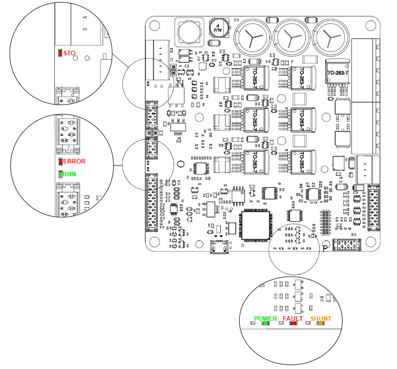
Jupiter Servo Drive provides information through 6 signalling LEDs:
- Supply and operation: 3 LEDs next to the Absolute encoder connector.
- CANopen communication: 2 LEDs next to the CAN connector.
- STO: 1 LED next to the STO connector.
Jupiter with EtherCAT includes 3 more LEDs for the EtherCAT fieldbus status.
Power and operation signalling LEDs
Three LEDs situated next to the Absolute encoder connector indicate the supply and operation status. Next table shows the meaning of each LED:
LED | Colour | Meaning |
|---|---|---|
POWER | Green | LED is on when internal power supply is working. |
FAULT | Red | LED is on when a fault or error has occurred. |
| SHUNT | Orange | LED is turned on with the shunt braking resistor is activated, indicating that maximum user voltage has been exceeded and power is being dissipated. |
CAN signalling LEDs
Two LEDs besides the CAN connector provide information about the CANopen communication status, according to CiA 303-3 recommendations. The red LED is ERROR LED and green one is RUN LED.
ERROR LED indicates the status of the CAN physical layer and errors due to missed CAN messages (sync, guard or heartbeat). Next table the meaning of the ERROR LED states:
ERROR LED state* | Concept | Description |
|---|---|---|
Off | No error | Device is in working condition. |
Single flash | Warning limit reached | At least one of the error counters of the CAN controller has reached or exceeded the warning level (too many error frames). |
Double flash | Error control event | A guard event (NMT-slave or NMT-master) or a heartbeat event (heartbeat consumer) has occurred. |
Triple flash | Sync error | The sync message has not been received within the configured communication cycle period time out. |
On | Bus off | The CAN controller is bus off. |
RUN LED indicates the status of the CANopen network state machine. Next table shows the meaning of the RUN LED states:
RUN LED state* | Concept | Description |
|---|---|---|
Off | Off | The device is switched off |
Blinking | Pre-operational | The device is in state PREOPERATIONAL |
Single flash | Stopped | The device is in state STOPPED |
On | Operational | The device is in state OPERATIONAL |
*See a detailed description of the states in the next table:
* Possible LED states | Description |
|---|---|
ON | The LED is always on |
OFF | The LED is always off |
Single flash | One short flash (~200 ms) followed by a long off phase (~1000 ms) |
Double flash | Sequence of 2 short flashes (~200 ms), separated by an off phase (~200 ms). The sequence is finished by a long off phase (~1000 ms) |
Triple flash | Sequence of 3 short flashes (~200 ms), separated by an off phase (~200 ms). The sequence is finished by a long off phase (~1000 ms) |
Blinking | On and off with a frequency of ~2.5 Hz: ON for ~200 ms followed by off for ~200 ms. |
Note that the specified timings can vary in up to ±20%.
STO signalling LED
A LED next to the STO connector indicated the status of the Safe Torque Off system. The states of the STO LED are indicated in the following table:
STO LED state | Concept | Description |
|---|---|---|
Off | STO deactivated | The STO is deactivated (STO inputs are energized) and the drive operates normally. |
On | STO activated | The STO is activated (some STO input opened) and the drive power stage is disabled. |
EtherCAT signalling LEDs
The Jupiter Servo Drive with EtherCAT fieldbus includes 3 more LEDs to indicate communication status according to EtherCAT specification.
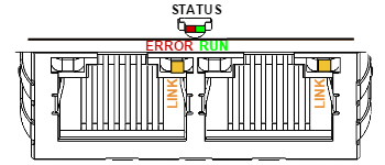
The EtherCAT bicolor green/red LED indicates the EtherCAT state machine status. The green LED is the RUN LED, and the red LED is the ERROR LED. Next table shows their states meaning:
RUN LED state | EtherCAT slave status | ERROR LED state | EtherCAT slave status | |
|---|---|---|---|---|
| Off | INIT | Off | No error | |
| Blinking | PRE-OPERATIONAL | Blinking | Invalid configuration | |
| Single Flash | SAFE-OPERATIONAL | Single flash | Local error | |
| On | OPERATIONAL | Double flash | Watchdog timeout | |
| On | Application controller failure |
For high severity errors inside the Jupiter Servo Drive, an special LED state has been developed:
| Status | Signalling | RUN LED state | ERROR LED state |
|---|---|---|---|
| Internal error | Interleaved blink | Blinking (Initial status: OFF) | Blinking (Initial status: ON) |
The frequency of the blinking is different than the used for communication and is product dependent.
The other two LEDs are situated in the EtherCAT connector. Each connector has two LEDs, but only the yellow LED is used. The LINK LED indicates the state of the EtherCAT physical link activity:
| LINK LED state | Slave State |
|---|---|
| Off | Port closed |
| Flickering | Port opened (activity on port) |
| On | Port opened (no activity on port) |