Electromagnetic Interference Issues With Servo Drive Systems
Overview
Electromagnetic interferences are an issue that affects servo drives and the electrical equipment surrounding them, and it can cause several inconveniences:
- Incorrect reading of the feedback devices can cause control problems and motor glitches.
- Communication problems and loss of data or synchronism.
- Interference to surrounding circuits near the servo drive system.
- No compliance with Electromagnetic Compatibility (EMC) standards.
Fortunately, understanding the problem with the models presented in this document should allow solving most of the EMC problems with simple actions on the system design stage (preferred) or on the field. This document is intended to show a framework to understand and solve the problems instead of repeating once again vague rules of thumb such as connect the protective earth, shield the cables, or add ferrites.
Understanding EMC on Drives
EMC Basics
Electromagnetic compatibility (EMC) is the ability of electrical equipment and system to function satisfactorily in their electromagnetic environment, by limiting the unintentional generation, propagation, and reception of electromagnetic energy which may cause undesired effects such as Electromagnetic Interference (EMI) or even physical damage in the operational equipment. It is essential to differentiate the 3 elements involved in EMI:
- Source
- Coupling Channel
- Victim
Voltage Divider Model
To quantify the impact of the interference on the victim, there is a simple yet practical model to know which will be the induced effect. It considers the source - channel - victim as a voltage divider. Since most problems happen with transient and AC signals, instead of resistors, the divider should be made with impedances. For simplicity, it is usually not necessary to use complex numbers for Z but just use absolute values of impedance and voltages instead.
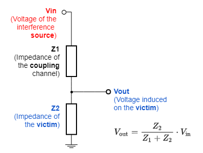
Where:
Vin is the amplitude of the noise source.
Vout is the voltage induced on the victim circuit.
Z1 is the impedance of the coupling channel. The Z should be calculated at the fundamental frequency of the interference.
Z2 is the impedance of a victim at the given frequency. For a purely resistive circuit, this Z is the resistance. For a capacitive input Z = 1 / (2 · π · f · C).
f is the fundamental frequency of the interference. ![]() Note that sometimes the problematic frequency is NOT the obvious one. For instance, the motor phase's fundamental switching frequency 10 kHz ~100 kHz typically does not create problems. Instead, the problems come from the harmonics between 10 MHz and 1 GHz. The same happens with most hard switched signals and crystals, always consider the harmonics that are related to the transitions, not only the main frequency.
Note that sometimes the problematic frequency is NOT the obvious one. For instance, the motor phase's fundamental switching frequency 10 kHz ~100 kHz typically does not create problems. Instead, the problems come from the harmonics between 10 MHz and 1 GHz. The same happens with most hard switched signals and crystals, always consider the harmonics that are related to the transitions, not only the main frequency.
Understanding this model quantitatively will make many of the actions indicated next crystal clear. Following is a description of the source, channel, and victim:
EMI Source
The EMI source is the generator of electromagnetic disturbance. It can be power electronics switching, relays, power line surges, electrostatic discharges (ESD), lightning, RF equipment, etc.
EMI Sources from the Environment
External interference sources can be categorized according to the EMC standards in the following categories:
- Electrostatic Discharges (ESD)
- Electrical Fast Transients (EFT)
- Surges
- Radiated Immunity
- Conducted Immunity
- Voltage Dips, Drops, and Interruptions. It usually affects AC drives only.
Each one has a standardized test that depends on the product category and environment. Otherwise specified, Ingenia servo drives are designed to meet IEC 61800-3: Adjustable speed electrical power drive systems - Part 3: EMC requirements and specific test methods.
EMI Sources from the Drive System Itself
The EMI source on a servo drive can come from communication buses such as EtherCAT or CAN, from DC/DC converters, or the high-frequency clocks. However, the most important interference source on a servo drive system is the power stage. Therefore, most interference issues are generated by the servo drive itself instead of coming from the rest of the installation or the environment. The power stage is by design a very powerful electromagnetic interference source during each switch of the power stage transistors. The emissions from a switching power stage depend on:
| Variable | Depends on | How to reduce emissions |
|---|---|---|
| DC bus voltage | Application | Lowering the DC bus voltage will reduce the EMI since the DC bus determines the amplitude of the interference. To determine if an interference issue is coming from the power stage, a practical tip is to reduce the bus voltage and check if is still happening. |
| Phase current | Application | The higher the current → the higher the conducted EMI. However, it is not always proportional to the current value and depends strongly on the motor impedance. |
| PWM frequency | Application / Design | Lowering the PWM frequency will reduce the average energy of the emissions. Note, however, that a single PWM transition can be enough to cause an error on a digital feedback or communication interface. Reducing PWM frequency may be ok to pass a certification emission limit, but it may not be sufficient to avoid problems. Note that in low inductance applications, a low PWM frequency can lead to excessive current ripple which affects conducted emissions. |
| Modulation scheme | Design / Application | The power stage modulation scheme and duty cycle of the output voltage waveform can have a significant effect on the even harmonics. At low frequencies, the duty cycle that could be related to motor speed and application needs can vary significantly. |
| Power stage switching speed (di/dt, dV/dt) | Design | The design of the power stage determines the dV/dt and di/dt which correlate to the fundamental frequencies of the emitted interference. Typically, faster transistors such as GaN fets have a higher switching energy efficiency (the product I · V · t is smaller) but the frequency spectrum spreads to higher frequencies (typically at 10 MHz to 1 GHz). The opposite would be slow/soft switching transistors to reduce EMIs, but it goes against energy efficiency (except for ZVS or ZCS) as the area I · V during switching increases. The extreme case would be a linear power amplifier that has minimal EMIs but terrible energy efficiency. Ingenia power stages are usually designed to have the highest energy efficiency while keeping EMI within the standards. |
To get an idea of the frequency spectrum generated by the power stage we can consider the phase as a trapezoidal waveform with very short rise and fall times that can range from 200 ns to 5 ns depending on the power stage technology, operation point, and parasitic capacitances. The following graphs show the envelope of harmonics of that trapezoidal wave and how to estimate its magnitude.
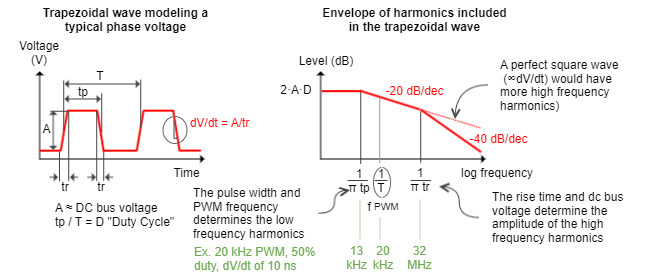
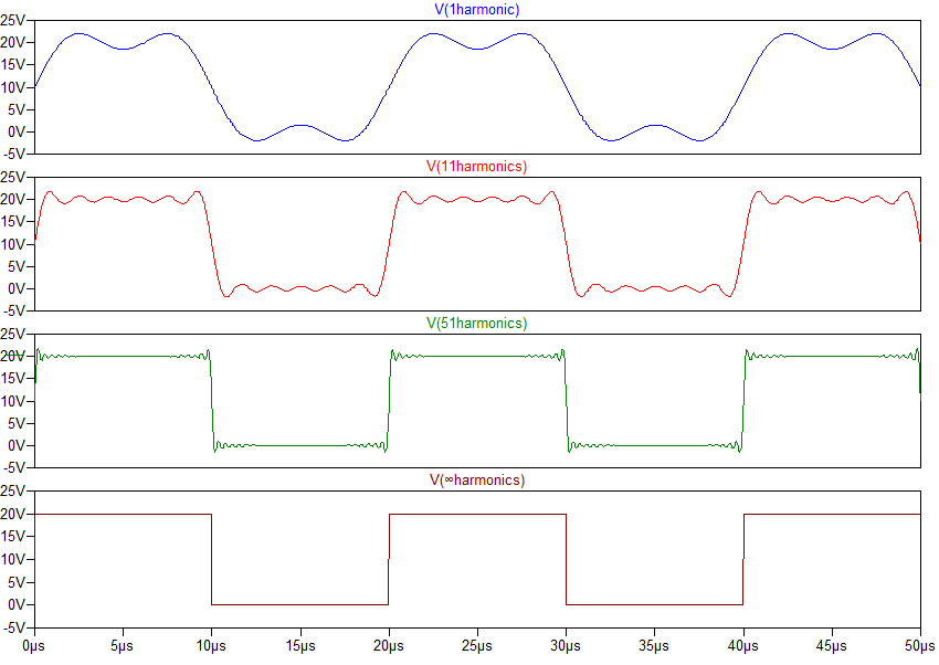
Although it may be counterintuitive, the more perfectly square the phase voltage is, the more high-frequency interference it will carry. Filtered motor phase outputs with a common mode choke, for instance, may appear uglier in the time domain (oscilloscope) but may cause fewer EMI problems. Changes in the duty cycle also affect the frequency spectrum. The following image shows the Fourier synthesis of a square wave of 20 V amplitude and 50 kHz depending on the number of harmonics:
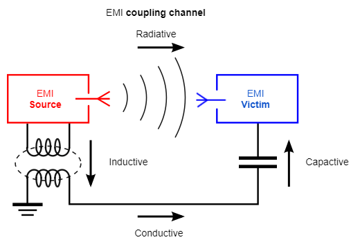
EMI Coupling Channel
The coupling channel is where the EMI is propagated to the victim. It can be summarized in 4 categories: radiative, conductive, inductive, and capacitive.
Note that many couplings do not necessarily occur on a single channel but as a combination of them. E.g. an inductive coupling from the motor cables to the encoder, being transferred via conductive coupling on the PCB to a communications port and then radiated through the communication cable.
The following table explains each channel and which actions can be made to mitigate it:
| Coupling channel | Description | How to mitigate the coupling |
|---|---|---|
Radiative (Far-field)
| Radiative coupling occurs when the source and the victim are separated by a large distance, typically more than a wavelength (λ). The source and the victim act as radio antennas: the source emits or radiates an electromagnetic wave that propagates across space in between and is picked up or received by the victim. The coupling depends mostly on the frequency, geometry, and length of the circuits. Most radiative couplings occur on cables that become an optimum antenna when their length is equal or greater to λ /4. With λ = c / f, where λ is the wavelength in meters, f the frequency in Hz, c the speed of light ≈ 3 · 108 m/s. For a 100 MHz signal λ ≈ 3 m, for 1 GHz, λ ≈ 30 cm. | Reduce cable length whenever possible, the shorter the better as it will be a less efficient antenna. |
Shield the EMI source, especially the motor phases when the drive is not embedded inside the motor housing. If it is not possible to shield the source, shield the victim. | ||
| Focus on the cables and grounding. Sometimes conducted interference becomes radiated through the cables and their shields or even structural elements. | ||
| Reduce dV/dt on signals that will be connected to cables. Ferrites are very useful for this. | ||
Conductive | Conductive coupling occurs when the coupling path between the source and the victim is formed by direct electrical contact with a conducting body, for example, a supply line, wire, cable, PCB trace, or metal enclosure. Conducted interference is also characterized by the way it appears on different conductors:
| Use galvanic isolation between signal circuits. This directly cuts the conductive path. Note that power supply isolation transformers have also large parasitic capacitances and may not solve some EMC issues. |
| If isolation is not possible, minimize grounding resistance and cable length whenever possible. | ||
Have a good, low impedance earthing with thick cables and ground planes (low R and L). Watch out for the corrosion of grounding connections. | ||
| Use EMC line filters at the power supply inputs. This helps prevent conducted EMI and is usually mandatory to meet EMC standards. | ||
Inductive (Near field)
| Inductive coupling or magnetic coupling occurs when a varying magnetic field exists between two parallel conductors typically less than a wavelength apart, inducing a change in voltage along the receiving conductor. In some way, it can be understood as a transformer where the primary is the EMI source and the secondary is the victim. The coupling depends on current variation (di/dt) and the distance and length exposed between source and victim. | Reduce the parallel area between source and victim. Like feedback cables and motor cables. |
Increase the distance between high current lines and other signals. | ||
| Route high current signals close to their respective returns paths to minimize the area. Example: twist cables + and - signals. Pack the motor phases together. | ||
| When planning the wiring, do not pass cables over the power boards. Near field inductive coupling is the predominant factor and causes problems with loose wirings. | ||
Capacitive (Near field) | Capacitive coupling occurs when a varying electrical field exists between two adjacent conductors typically less than a wavelength apart, inducing a change in voltage on the receiving conductor. The voltage variation (dV/dt) is the main factor. Also, the exposed area and distance between source and victim determine the parasitic capacitance. A typical capacitive coupling is long unshielded motor cables with feedbacks routed in parallel that cause encoder or hall sensor count jumps. | Electrical shielding is very effective. Shield the source with its own GND or PE. Shield the victim with a robust GND plane. |
| Increase the distance between conductors and reduce exposed areas. | ||
| Isolators or optocouplers are useful but only the ones with a low parasitic capacitance that are tolerant to high common-mode interference. |


When encountering interference problems, most people's first reaction is to believe the channel is radiated. However, usually, the origin of the problem is a conductive, inductive, or capacitive coupling with radiation being a secondary coupling channel.
EMI Victims
The EMI Victims are the circuits affected by the interference source which is coupled through the channel. Whether this creates a problem or not will depend on the amplitude of the interference on the victim and what this amplitude causes to the receiver: a digital level change, a small amplitude variation, loss of data, or even physical damage to the circuits.
Depending on the victim's circuit the level of immunity can vary. The following table mentions several ways in which immunity can be improved:
| Victim circuit | How to improve immunity | Effect |
|---|---|---|
Digital Feedback devices Encoders Absolute Encoders | Differential signals instead of single-ended | Common mode interference becomes less important if the receiver is fully differential, as with feedbacks whose physical layer is RS422 or RS485. |
| Use receivers with high hysteresis | High hysteresis robust receivers (like the ones used in Ingenia Drives) reject spurious events better. | |
| Reduce the impedance of the receiver | The lower impedance at the receiver side reduces the effect of most EMC problems by minimizing the Z2. This does not necessarily mean adding low-value resistors which would increase power consumption, sometimes 100 pF capacitors to GND can do a great job at reducing Z2 at high frequencies. | |
ESD protection | Clamping protections are necessary to protect the inputs against transient events that could damage the input. | |
| Termination resistors | Ensure the transmission lines are correctly terminated with appropriate resistors (100 Ω ~ 220 Ω). This helps avoid reflections but also makes the line more immune. AC terminations (resistor in series with a capacitor) can be very effective and have the advantage that reduces power losses. | |
| Analog filters | Analog low pass filters can be very effective at rejecting high-frequency interference. These filters, however, cannot add too much delay which could cause motion control or reading problems. | |
| Digital filters | Ingenia Drives include digital filters that reject spurious interference or unwanted readings. Digital Encoder Information | |
| CRC (for absolute encoders only) | CRC Error detection ensures that the data from absolute encoders is correct. This is an essential feature for a noise-tolerant drive system that is included in protocols like BiSS-C. In the case of SSI choose variants that include CRC as BP3 or Zetlex SSI6. In SSI without CRC, a single wrong bit can make a huge glitch on the drive system that can cause mechanical failures or large current peaks. | |
| Gray coding | Gray coding reduces the angle effect of a single bit error. | |
| Hall effect sensors | Push-pull style hall sensors instead of open drain hall sensors | Most digital hall effect sensors used on motors have an open drain or open collector output for some historical reason. This means that when the signal is "high" it is very susceptible to interference. Push-pull output hall sensors are strongly recommended as they provide much better interference immunity as well as symmetrical delays. |
| Low-value pull-up resistors | With open-drain hall sensors, an input resistance ≤ 1 kΩ will reduce the impedance and delays. | |
| Analog filtering | Since hall sensors usually switch at some kHz at the maximum motor speed it is easy to filter them against MHz interferences. Care should be taken not to filter too much and create a phase delay that causes poor motor commutation efficiency at high speed which leads to high current peaks. | |
| Digital filtering | Ingenia drives not only include analog filtering but digital filter options to reject halls unwanted transitions. Digital Halls Information | |
| High hysteresis inputs | Schmitt triggered inputs with high hysteresis are always used to avoid unwanted transitions. | |
| Analog feedbacks, resolvers, torque sensors | Analog filtering | Analog filtering is essential to avoid incorrect measurements as well as ADC aliasing. |
| Terminations | Differential analog signals should be terminated to make them robust. Capacitive terminations also provide good results. | |
| Good grounding | Analog signals can be susceptible to a few mV, to avoid conductive noise problems using a specific analog ground. | |
| Communications | Interface | Each communication interface has a different level of immunity depending on the physical and communication layers. The interfaces could be sorted from more robust to least robust in the following order: (1) EtherCAT, (2) CANopen, (3) Ethernet, (4) RS485/RS422, (5) RS232, (6) UART, (7) SPI / MCB, (8) USB. Note that the exact order can change from system to system. |
| Shielding | Cable shielding is always recommended, especially when the cable is not protected by a conductive enclosure. | |
| Isolation | The isolation of the communication port (which is intrinsic in EtherCAT / Ethernet) is a determining factor in interference immunity. When using fully isolated interfaces it is very useful to connect the GND or return the communication interface to the cable shield. Robustness will be maximized and the isolation will cut any ground loop. | |
| Termination | Follow the recommendations on termination resistor topologies and use fail-safe receivers or biasing resistors. | |
| Code detection and correction | Communication protocols with parity detection, CRC, or other error correction algorithms are a must. | |
| Power supplies, DC/DC converters | Filter and decoupling | When the power supplies are the victims filtering the inputs with differential or common node filters is the best option. |
| Transient voltage suppressor (TVS) | Power supplies are relatively immune to ESD (pF) due to their big capacitance (µF), however, they can be impacted by surge and EFT. High power voltage clamping devices such as TVS diodes and or varistors should always be used. |
The EMC Model for a Drive System
The following figure shows a simplified electrical model that emphasizes the main elements involved in EMC in a servo drive system. Note that many elements involved in EMC cannot be found on the "schematics" or "wiring diagrams" because there is an alternative "invisible" schematic that includes parasitic elements.
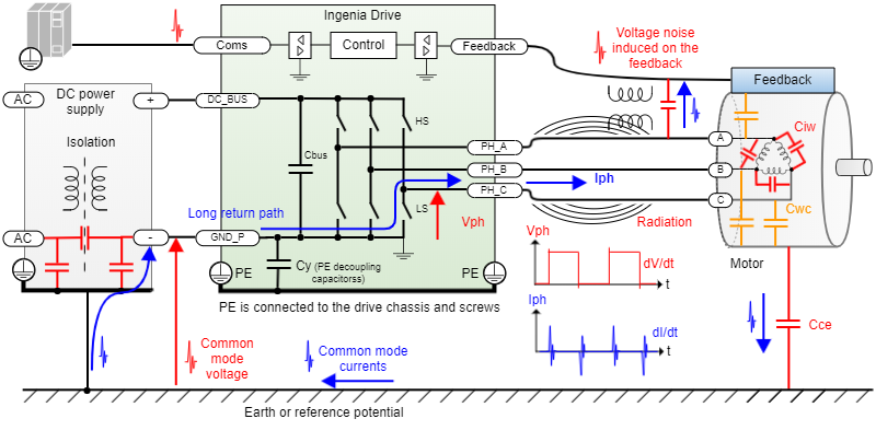
The motor has a strong impact on the overall EMC of the drive system. Its inductance and resistance affect low-frequency harmonics, but more important are the parasitic capacitances that cause unwanted current peaks on each switching:
- Interwinding capacitance (Ciw). Which tends to be in the order of nF. This causes large current peaks on the phases that couple inductively to other circuits.
- Winding to chassis capacitance (Cwc). Also in the order of nF or pF which causes current peaks to the chassis, radiated and common mode issues.
- Stator-rotor capacitance causes bearing currents and premature failures on high voltage drives (not included in the drawing).
- Motor chassis to earth capacitance depending strongly on where the motor is installed (this capacitance becomes negligible with good motor grounding to the drive).
As can be deduced, even when the average current is zero, large current peaks (in the order of amps) are happening each time the phase changes its voltage. These peaks oscillate and resonate between the parasitic circuits such as cable inductance and parasitic capacitances and cause many of the EMC problems. Indeed they can be radiated by the motor cables or the motor chassis itself.
Motor design and wiring have a big impact on EMI
Depending on the motor and wiring, the same servo drive can work perfectly, have zero EMC issues, or have big interference problems and not meet EMC standards. The ideal motor should have low parasitic capacitances and should have good grounding connections to its chassis.
The following explains why the recommendations repeated on every installation manual are so useful.
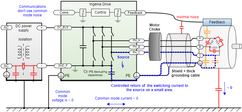
Effect of Grounding the Motor, Shielding the Phases and a Choke
The main recipe to solve most emissions problems on servo drives is a combination of the following:
| Power stage emissions mitigation action | Why it works |
|---|---|
| Motor chassis grounding | Grounding the motor chassis and provide a good low impedance (short thick PE cable) between the motor chassis and the drive chassis/power ground is very effective. This allows a return of the interference to the source in a small area. If a direct connection to GND_P is not possible for electrical safety, the connection can be made through a decoupling capacitor (included in many Ingenia drives). This sole chassis connection can be more effective than an input line filter. If the motor and drive are physically close, the connection can be made using the structure of the motor itself, with no need for an extra cable. |
| Grounding planes | A good grounding plane (earth) has very low resistance and inductance, reducing the common-mode voltage if there is a common mode current. This prevents problems with communication interfaces and devices that are connected to other reference points. Sometimes the grounding plane can be the heatsink of the system or the structure of the actuator. |
| Motor choke | Add a motor choke as close to the drive as possible. This will limit the di/dt and dV/dt since it increases the impedance at high frequencies while allowing the low-frequency currents to pass freely. There are several common mode choke types, some of them can be mounted on the interface board or cable mounted. There are many materials, with nanocrystalline ferrite being very effective. Refer to the product manual to see appropriate ferrites. Never pass the PE cable through the motor choke. This will magnetically couple the interference to earth amplifying it. |
| Motor phases shielding | Shield the motor phases (after the choke) to minimize the capacitive coupling and the radiated emissions. While this is not necessary on motor integrated servo drives, this is a must for any system where the drive and the motor are separated. |
| Motor phases twisting | Twist or braid the phases together and keep them separated from other signals to minimize magnetic coupling. Avoid having the phase wires spread or uncontrolled since the magnetic field depends on the area between phases. Note that cable shields are not effective at shielding magnetic fields. |
| Phases passive filtering | In systems that require extremely low EMI, have very long motor cables with other signals near the phases, sometimes it is necessary to add passive "LC" dv/dt filters. This option can eliminate the frequencies above the cutout frequency, however, it should be implemented carefully since it has many drawbacks for a servo drive system such as LC resonance causing "new" EMI peaks, voltage overshoot exceeding safe levels, slower control causing loss of performance and delay, current reading issues. |
Example of a low EMI solution.
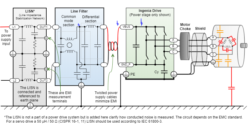
Effect of Power Line Filter
Due to the intrinsic noisy nature of the power drive systems, a line filter is usually necessary when conducted emissions levels should be met. In some cases, conducted EMI is radiated and causes radiated emissions. A combination of differential and common mode filters is usually necessary. When various drives are close, the line filter can be shared between various drives with a common DC bus.
| Conducted emissions | The main source on a drive system | Mitigation |
|---|---|---|
| Differential | The ripple of the DC bus current has the origin on lower frequencies (PWM and first harmonics) and is related to the commutation, motor electrical characteristics, current of the application, etc. | An LC π filter (Capacitor - Inductor - Capacitor) on the DC bus is usually the most effective way to remove this ripple. On a servo drive, it is recommended to have filters with large capacitance (in the order of 100s of µF) to allow regenerative braking and rather smaller value inductors to make a second order low pass filter. |
| Common mode | Capacitive coupling on the drive and motor itself to earth. Inductive coupling of power elements to other parts of the system. Higher frequency switching harmonics. | Firstly, apply the points indicated above: motor choke, grounding, short motor cables that could be shielded. Then a line filter with a common mode filter will do the job. Typically a single or dual-stage filter is enough. A choke may be needed if the problem is on a higher frequency, radiated. |
To quantify the conducted emissions, they are measured with a LISN (Line Impedance Stabilization Network) that "converts" supply ripple currents to a voltage that is AC coupled to a spectrum analyzer. Although this LISN is never found on a power drive system, since it is an EMC laboratory device, it has been included here to clarify electrically how the filter can reduce emissions. Shorting the ripples and high-frequency paths with capacitors while blocking them inductive elements.
Some interesting points regarding line filtering:
- The filter should be close to the interference source (the servo drive), and it is ok to share it between various drives if they are on a well-grounded board or cabinet.
- To avoid radiation from the power supply cables, twist them and minimize the area between them.
- In some cases where the power supply is fully isolated, it is possible to connect GND_P to Earth on a single point. This reduces conducted emissions substantially but can have side effects as ground currents, safety problems, and reduced immunity to transients.
Some battery-powered systems do not have conducted emissions requirements and the filter can be avoided to save weight and cost. However, take care not to have radiated problems from the supply cables.
Always dimension the filter after following the previous recommendations regarding the choke, PE wiring, and phases shielding. This will allow using a smaller filter.
Several Problems are Solved when the Drive is Integrated on the Motor Enclosure
When the servo drive is integrated into the motor, the switching interference is enclosed on the chassis that acts as a Faraday cage. Wiring is minimized in length, coupling and emission lines can be handled in a controlled environment not dependent on the end application wiring and installation and the installer EMC skills. This can be achieved using small modular servo drives.
Summary
EMC is not just passing certifications. It is ensuring that the system is robust and will function without causing problems to nearby devices.
Having a good understanding of EMC and applying it during the initial system design phase will solve most problems before they even arise.
Keeping the source-channel-victim frame in mind is very practical to solve these problems. The EMI mindset looks beyond the "pdf wiring diagram" and tries to find parasitic coupling paths between sources and victims. Sometimes, however, it is necessary to use the oscilloscope, spectrum analyzer to measure what is happening.
When facing interference emission problems start with the obvious source: the switching of the motor phases, and check if the "rules of thumb" of short motor cables, good grounding, shield the phases, and use motor choke have been applied. After that is 100% clear, proceed with other less probable hypotheses.
If having interference on the feedbacks consider digital filtering as it has the lowest cost and can be applied fast. If possible choose robust feedbacks with differential interfaces and CRC.
Having the drive close to the motor and if possible inside the enclosure solves most of the EMC problems encountered in servo drives, it maximizes the chances of passing EMC certification and does all at the lowest cost and with maximum simplicity.