Latency in EtherCAT Servo Drives
Definition of latency
This document explains the concept of latency in the world of EtherCAT servo drives. Latency is a wide term applicable to different processes occurring in a servo drive and depending on the stage, its definition may change. This article defines latency as:
The number of network cycles between the transmission of a PDO message from the EtherCAT Master and the reception of a PDO message from the EtherCAT slave containing the same value.
PDO means Process Data Objects. It is highly recommended to have some basic knowledge about EtherCAT to understand this article properly.
Why have we chosen this definition?
As a servo-drive manufacturer, and, therefore, as a slave (of the EtherCAT network) component designer, it is required to think about the needs of the element which is going to command the servo-drive: the master. The role of the master is wide and admits multiples definitions too, so the question becomes: when is the latency a critical requirement for an EtherCAT master? Excluding some specific applications, the main concern regarding the latency is when the master needs to obtain certain data from the slave inside a specific window of time. Examples of this are:
A master closing control-loops using the slave's feedback
A highly-responsive system where the master needs to react as fast as possible to sudden changes in its working environment
In these examples, the master requires information from the slave(s) of the network. On modern system architecture solutions, this interaction between master and slave is done through field communications protocols such as CANopen or EtherCAT. These kinds of protocols work with a deterministic cycle rate of messages. This means that the slave has a predefined slot of time to provide the information that is later taken by the master. Therefore, the time a slave takes to deliver information to the master can be measured in cycles of the field network.
The slave could obtain data earlier than the time it takes to transmit it through the network, but from the master point of view, the data is available on that slot of time.
Let's take a closer look at the example where the master controller is closing a control loop using the feedback information from the sensors connected to the slave. Let's take the following:
The master closes a position control loop using the actual position feedback provided by the slave.
The slave closes the velocity control loop using the target velocity commands sent by the master.
The master and the slave are connected through an EtherCAT network with a cycle time of 1 ms.
Under these conditions, the master will send new target velocities every 1 ms and the slave will return the actual position values to the master at the same rate. The question in this case is:
How long does it take for the slave to receive a target velocity value after the master has received the actual position value read by the slave?
The answer to this specific question is 2 network cycles for Ingenia Summit servo drives. Read the following sections for further explanations.
Delay vs latency concept
Latency is sometimes defined as the time between a command is transmitted to a servo-drive and the time it takes to update its output. In this article, this time is defined as system delay. This time is usually much smaller than the previously defined latency. Let's put some numbers to the previous example:
The default velocity control-loop rate of an Ingenia Summit servo-drive is 20 kHz
Assuming the worst-case scenario, the time it takes to an Ingenia servo-drive to modify its output voltage after the reception of a new target velocity is approximately 150 μs. On the other hand, the time required to take a new position since the reception of a new target velocity is less than 150 μs (it is obtained before the output voltage is updated). However, for this example, the master will receive this position actual value 2 ms after the reception of the new target velocity.
Update rate vs latency concept
In this article, the update rate is 1 divided by the number of times in a second that a network transmission is initiated. It is important to take this parameter into account when defining the latency in network cycles instead of the amount of time. Some practical examples are the following:
For an update rate of 1 ms (1000 network transmissions per second) and a latency of 2 network cycles, the latency in unit time is 2 ms.
For an update rate of 100 us and a latency of 3 network cycles, the latency in unit time is 300 us.
So the second case has a worse latency in network cycle units, but the end result, the latency defined as the amount of time, is better than the first one.
Ingenia summit drives are able to keep the 2 network cycles of latency up to an update rate of 4 kHz. For faster update rates, the latency cycle number is not deterministic.
How to measure it
The method used to measure the latency is directly linked with the definition of latency of the first section:
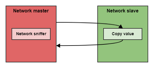
A master is connected to the slave through the network.
The network update rate is set.
A message is sent to from the master to the slave.
The slave copies the received value into another message, which returns to the master.
The master keeps sending the same message at the defined update rate until the value returned by the slave is the same.
A Network sniffer is used to capture all the transmissions.
In the picture, the sniffer is implemented inside the network master. However, it could be an external device.
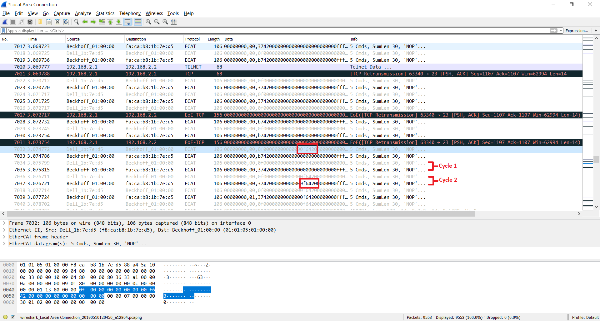
Coming back to the example, this is how latency will be measured:
EtherCAT master (TwinCAT in a PC) is connected to an Ingenia EtherCAT servo drive.
Wireshark (Network sniffer) is running on the same PC as TwinCAT.
A network update rate of 1 ms is set.
Target velocity and velocity demand are configured to be transferred at the network update rate.
In this example, the copy of the value sent by the master is directly the velocity demand.
Start transferring a target velocity value on every network cycle until velocity demand shows the same value.
Using the captures from Wireshark, the number of cycles is measurable.
How latency affects the performance of a system
The defined latency in this article can be interpreted as a known delay in the system. As any delay in a system, it has the following implications:
It worsens the reaction time of the system. This is especially critical for safety functionalities where the reaction time needs to be as fast as possible.
It increases the complexity of the system models. System models that can be used for simulation and find a control loop fine-tuning of the system become more complex. For example, if the master is implemented as a simple PID controller for the position loop, it should take into account the latency when closing the loop with the actual position values that receive from the slave.
It decreases the performance of closed-loops. The two factors above produce a decrease in the performance of the control loop, which basically means that the maximum reachable system bandwidth is lower than the ideal (zero latency) case.
Main contributors to latency and how to improve them
Almost every functional block inside a real-time system can affect the latency.
The processing time of every element inside the control loop chain.
The topology of the network.
The network communication protocol.
The number of devices in the same network.
The first step to decrease the latency of a system is to identify the main bottleneck of the chain. It is worthless to improve all the points mentioned above if there is a more severe one that masks any improvement applied to the other points.
However, this article tries to cover the topic with a general vision on specific EtherCAT systems, so let's see what improvement can be done on every element.
Latency contributor | Improvement |
|---|---|
The processing time of every element inside the control loop chain. | The first step is to remove any unnecessary process that consumes time in the middle of the control loop chain. This process must be executed at the end of a network cycle. 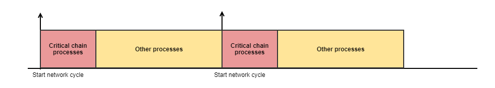 Secondly, there are two main strategies to decrease the processing time:
It is assumed that all the involved processes are optimized. |
The topology of the network | In applications where latency and determinism is a critical point, it is important to take a look at the different topologies of the market field bus protocols. For example, bus topologies are typically worse in terms of latency than daisy-chain ones. 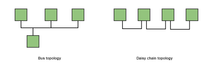 The main problem of bus topologies is that it usually requires some kind of arbitration to gain access to the channel, whereas in daisy-chain topologies one device could potentially have full control of the channel (usually the master). On the other hand, daisy-chain topologies allow using a single message for all the devices and process it "on the fly". That means that each device modifies its section of the whole transmitted message in the same network cycle the message has been sent. EtherCAT uses this daisy-chain topology precisely. The EtherCAT master is the only one that can initiate a transmission in the network. This message is transmitted through all the slave nodes which process the message on the fly. |
The network communication protocol | The network protocol itself could be one of the most relevant elements that increase the latency. Solutions that require multiple messages per data could add extra network cycles. On the other hand, full-duplex solutions usually add by default 2 network cycles. This is the case of EtherCAT. Due to the message processing "on the fly", by default, the minimum latency of any slave in an EtherCAT network is 2 cycles. This point could seem a drawback of the EtherCAT network, but this strategy allows keeping a very low latency at higher update rates when the number of network nodes increases. |
The number of devices in the same network | There are protocols extremely fast for point to point solutions that become worse for every new node that is added in the network. One clear example is a protocol based on a single SPI interface with 2 nodes. SPI is a master-slave protocol where the master requires to initiate the transmission of a message. If two nodes are connected to the same interface, it means that the master needs to initiate two transmissions to obtain the data of the two devices. In comparison with a point to point SPI connection, in this case, the total update rate of the network will be less than half of the update rate with a single device. On the other hand, EtherCAT uses a daisy-chain topology and uses a single message per cycle for the whole network. Therefore the latency keeps constant and the update rate is only affected by the propagation time. Following the SPI example, if an EtherCAT network increases the number of nodes from 1 to 2, the resulting update rate remains practically constant. |
Conclusion
EtherCAT is one of the best field bus communication protocols in the industry for applications where high determinism and high update rates are required. Furthermore, Ingenia EtherCAT servo drives have been designed to obtain the maximum performance from this network reaching the minimum latency at high update rates.