Automatically resetting under-voltage fault
Description
When the supply voltage of the drive drops lower than a user specified voltage (for example 12V), an internal fault is generated by the firmware. When the fault has been detected, the drive is being disabled automatically. In order to enable the motor again, the board has to be reset or a manual fault reset from motion lab is needed. In some cases however, this rebooting of the board or an intervention needed by Motionlab can be undesired. This example describes a macro which automatically enables the motor if the supply voltage is high enough again after a user-undervoltage fault occurred.
| File | Macro | Description |
|---|---|---|
| ResettingFaultV1.ximf | 1 | Implementation 1: manually enabling the motor |
| ResettingFaultV2.ximf | 1 | Implementation 2: Enabling using motor on/off |
| ResettingFaultMacro0.ximf | 0 | Macro 0, setting status to 0 and calling the macro |
Note 1: You should either load macro V1 or V2 into Macro 1. They both have the same functionality, but are different implementations.
Note 2: Macro 0 should be loaded. In case multiple macros are running, this macro should be edited.
Note 3: If another Macro is already loaded into macro 1, one could use the move button to move the newly loaded macro to another macro.
Instructions used
The notes use the following instructions
| Instruction type | Instruction | Description | Comments |
|---|---|---|---|
| Motor control | Motor ON | Enables the servo drive | |
| Program flow | Macro jump | Jumps to a specific macro number | 'Go To 'equivalent |
| Program flow | If | Conditional jump | It allows execution of a group of program lines if the specified expression is true |
| Set Variable | Registers | Executes an incremental or absolute move | Sets the value of a register or performs mathematically expressions such as 'ADD' and logical expressions such as 'AND'. |
Materials used
Any board. Tested on a Neptune running Firmware release 2.3.1.
Program Example
This description only handles the macro itself. The macro should be called in macro 0 (or another macro) as well. Please note that the status variable (0x2c00 0x03) should be set to 10 when the macro starts. The macro is automatically calling itself again, so it keeps on repeating.
General description and macro-flow
In order to be able to guarantee the correct flow and reduce the amount of computations every cycle, the macro has been written in a state machine using 2 states. Register 0x2c00 subindex 0x03 is the state variable, with the following possible states:
- 10. No error detected. Checking for new errors.
- 20. Error detected. Checking if voltage is raised again. If so, restart motor.
In pseudo-code, the macro is doing the following:
Pseudo-code
if (state == 10)
	ErrorCheck = (DriveState) && 8 //Error if 4th bit is high, so 1xxx && 1000
	if (ErrorCheck == 8)
		//Error detected. Check if the error is under-voltage (means that error code is 0x3221)
		if (ErrorCode) == 0x3221
			// User under-voltage detected. Move towards next state
			state = 20;
		end
	end
end

//User under-voltage detected. Check if the voltage already raised. If so, restart motor
if (state == 20)
	Threshold = UserUnderVoltage + 2.5;
	if (DriveVoltage >= Threshold)
		EnableMotor();
		state = 10;
	end
end
Used Registers
Used registers from the Firmware.
| Register | Sub Index | Description | Comment |
|---|---|---|---|
| 0x603F | 0x00 | ErrorCode | The drive error code. User under-voltage = value 0x3221 (hex) |
| 0x6041 | 0x00 | Status of the drive | If an error occured, 4th bit is a 1 (1xxx). |
| 0x6040 | 0x00 | Drive Status | Sequence 128, 6, 7, 8 can be used for resetting, disabling, power on and enabling motor, respectively. |
| 0x2101 | 0x01 | Drive Voltage | The actual voltage of the drive |
| 0x2101 | 0x03 | User under voltage | The setting for the user under-voltage. Is set in protection within Motionlab |
Used general purpose registers.
| Register | Sub Index | Description | Comment |
|---|---|---|---|
| 0x2C00 | 0x03 | State of the macro. | 10 = No error, 20 = Under-voltage detected |
| 0x2c00 | 0x04 | ErrorCheck | Is b1000 (=8) if an error has been detected |
| 0x2c00 | 0x05 | Threshold | The user under-voltage value + a 2.5V threshold voltage. |
State 10: Detecting error
In this part of the macro we are checking if the drive is in error state and if so, if the error is indeed user under-voltage. If the error is not user-undervoltage, the status remains 10, so during the next run the macro will again check if the drive is still in error.
Instruction 0:
This instruction is simply checking if the State variable is equal to 10. If so, it continues, if not, it jumps towards the label 'EndIf10'
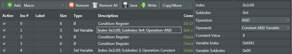
Instruction 1:
The statusword (register 0x6041 - Statusword) is giving the status of the drive. As can been seen in the table below, the drive is only in fault mode, if the 4th bit is 1 (1xxx). So to check if the drive is in error, we should perform a logical AND operation, to verify whether this bit is high or not. So we want to do: Regiser 0x6041 && 0000 0000 0000 1000. However, it is not possible within the composer to write binary values, only hex or decimal. So instead of 0000 0000 0000 1000 we have to write simply 8. See the screenshot below.
Value (binary) | Status |
|---|---|
xxxx xxxx x0xx 0000 | Not ready to switch on |
xxxx xxxx x1xx 0000 | Switch on disabled |
xxxx xxxx x01x 0001 | Ready to switch on |
xxxx xxxx x01x 0011 | Switched on |
xxxx xxxx x01x 0111 | Operation enabled |
xxxx xxxx x00x 0111 | Quick stop active |
xxxx xxxx x0xx 1111 | Fault reaction active |
xxxx xxxx x0xx 1000 | Fault |
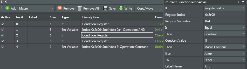
Instruction 2:
Checks if the previous AND operation is equal to b1000 (=8 decimal). Since the if-statement is only able to work with dec or hex, we have to an 8 here at the constant value. If the drive is in error, the macro continues. If not in error, it jumps to the end.
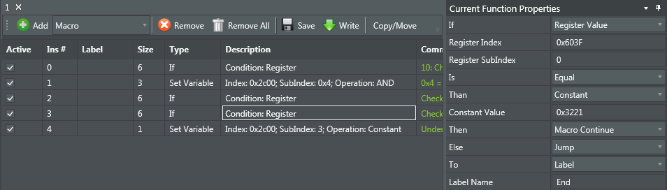
Instruction 3 and 4:
This instruction is only run if the drive is in fault modes. The instruction is checking if the error in register 0x603F 0x00 is equal to the user under-voltage error code (= 0x3221). If this is the case, the status variable is changed from 10 to 20 by instruction 4. If the error code is different, instruction 3 jumps towards the end.
Note the difference in the Constant Value field between instruction 2 and 3. In instruction 2 it is a decimal value, in instruction 3 a hex value (starting with 0x).
State 20: Enabling motor if voltage increases
In this second part of the macro, it has been verified that the drive is in the fault 'user under-voltage detected'. Now the macro is going to check if the voltage has been raised above to the minimum value + a threshold, if so, the motor will be enabled again.
Two different implementations are possible. The first one is manually changing the register value regarding the drive fault (0x6040 0x00). Changing this value into 4 different values 128, 6, 7 and then 8 sequentially, will reset, disable, power on and enable the motor, respectively.
The second implementation uses the motor off/on block in the composer. To use this, first the fault has to be reset (previous as in the first method, by changing 0x6040 0x00 towards 128 and then to 6). After this reset, motor off and motor on has to be used to be able to enable the motor. Once this has been done, the macro goes back to state 10.
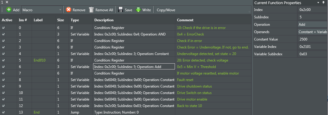
Full macro using the first implementation (manually changing the status of the motor):
Full macro using the second implementation (using the motor on/off instructions):
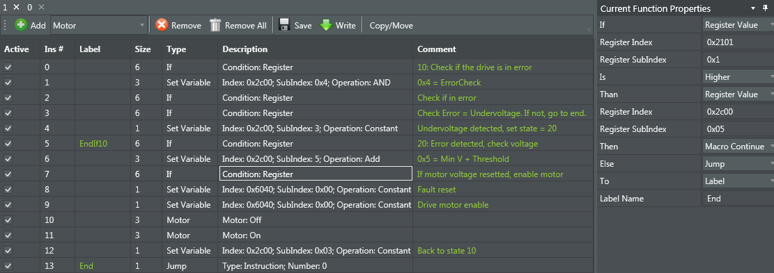
Instruction 5,6 and 7
Instruction 5 is checking if the macro is in state 20, so if an user under-voltage fault has been detected. If so, it continues, if not, the macro jumps towards the 'End' label.
Instruction 6 (see plot 'First implementation') is adding a threshold of 2.5V towards the user under-voltage parameter set in motion lab (written into 0x2101 0x03) and writes the result towards general purpose register 0x05.
Instruction 7 (see the plot 'second implementation') is checking if the real voltage of the drive (stored into register 0x2101 0x01) is higher than the value stored in 0x05. If so, the motor will be enabled, if not, the macro goes to the 'End' label.
Instruction 7-11 or 12
The next instructions are enabling the motor, using one of the two methods as described above.
After the motor is being enabled, the status variable (general purpose register 0x03) is being changed towards 10 again.
Looping the macro
The last instruction is a jump instruction, back towards instruction 0. So the macro keeps on running all the time. Right now, no wait instruction is implemented. But one could consider adding a wait instruction of for example 1000 ms. Keep in mind that the wait instruction should be added just before the jump instruction, and the 'End' label should be moved towards this wait instruction.
Notes
- Before the macro is run, the register 0x2c00 0x03 (status) should be made 10.
- If multiple macro's are running, it might be needed to change the general purpose registers used by this macro.
- If the user under-voltage is being reset outside this macro, the macro will try to enable the motor as well (it is still in state 20).
- A wait instruction could be added to reduce the computations.
- This macro should be working with any of the boards. It has been verified and tested with a Neptune, running FW 2.3.1