
Description
This macro task is reading an internal value, corresponding with an error code internally generated (not by the macros). The value of the error code will be displayed by enabling the digital outputs 1 up to 4, which in their turn can be connected to LEDs to display the error value. By using the 4 digital outputs, up to 16 different error codes can be displayed.
To reduce the length of the composer code, some binary mathematics are used.
The code is written and tested with a Neptune, which has only 2 GPOs. Therefore just 2 error codes are being displayed. The code is easily extensible though.
|
File |
Macro |
Description |
|---|---|---|
|
ShowingBitsFull.ximf |
0,1,2,3 |
The full program for tuning on/off the GPOs |
|
ShowingBits.ximf |
1 |
Macro to check error code and decide which GPOs should be changed |
|
MacroEnableGPO.ximf |
2 |
Macro which enables the GPO as written in GPR 0x10 |
|
MacroDisableGPO.ximf |
3 |
Macro which disables the GPO as written in GPR 0x10 |
Notes
This example is written for the composer in Motion Lab V2.10.2.
The instruction ' Set Output' is not working correctly in this Motion lab version, therefore macro 2 and 3 are used to manually change the outputs.
Program Example
This program contains 4 different macros, see the table underneath for a description of what each macro is doing. In this example the focus will be on macro 1.
|
Macro Number |
Description |
|---|---|
|
0 |
Calling macro 1 (on startup of the drive) |
|
1 |
Main loop. Checking the error code (in register 0x2C00 0x03) |
|
2 |
Macro to enable GPO |
|
3 |
Macro to disable GPO |
General description
The macro is checking an error (written in 0x2C00 0x3). The GPOs are set high according to the (binary) error, as displayed in this table:
|
Error (BIN) |
Error (DEC) |
Bit 1 |
Bit 2 |
|---|---|---|---|
|
00 |
0 |
False |
False |
|
01 |
1 |
True |
False |
|
10 |
2 |
False |
True |
|
11 |
3 |
True |
True |
For ease of understanding, the behavior of the macro is here explained in pseudo-code. Basically just for every bit separately is checked if the corresponding GPO should be changed.
If Error && 0x1 == 0x1
	GPO = 1;
	EnableGPO( GPO );
else
	GPO = 1;
	DisableGPO( GPO );
end

If Error && 0x2 == 0x2
	GPO = 2;
	EnableGPO( GPO );
else
	GPO = 2;
	DisableGPO( GPO );
end
Used registers
|
Register |
Sub Index |
Description |
Comment |
|---|---|---|---|
|
0x2C00 |
0x03 |
Error Code |
This is the error code that will be visualized by the macro |
|
0x2C00 |
0x04 |
Temp output |
Temporary output of logical AND, used for the if-statements |
|
0x2C00 |
0x10 |
Macro Explanation
The whole code used to make 1 bit high is shown in the following picture. Instruction 7 is the first line of the 3nd bit to check. This code can be repeated for all the following bits in the error code. So if you want to check an error code of length 3 (001 for example), you need to copy this code 3 times.
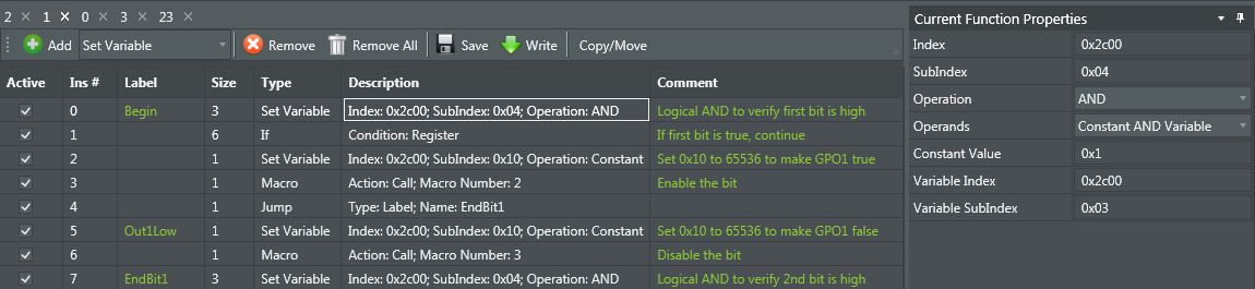
Instruction 0
In the figure above, the function properties of instruction 1 are shown. The instruction performs a logical AND with the error code (in GPR 0x03) and writes it into GPR 0x04. Since we are only able to give constant values as HEX or DEC, programming BIN checks is somewhat complicated. The constant value depends on which location of the error code you want to check. In the next table, the 'x' indicates the bit you want to check.
|
Error bit |
Constant value |
|---|---|
|
000x |
1 |
|
00x0 |
2 |
|
0x00 |
4 |
|
x000 |
8 |
The result of the logical end will be 1,2,4 or 8 respectively, if the bit is 1, and 0 if the bit is 0.
Instruction 1
The if-statement is checking if the result of Instruction 1 (written in GPR 0x04) is equal to 1,2,4 or 8, depending on which bit. In the screenshot we are checking 000x, so the value is 1.
If the result is 1, the macro continues to set the GPO high. If not, the macro jumps to the part where we set the GPO to false (label 'Out1Low').
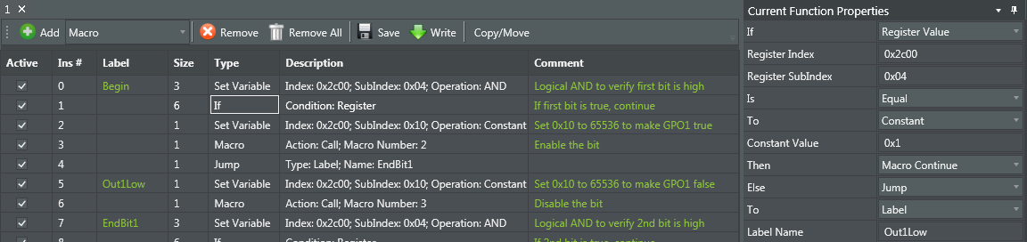
Instruction 2,3 and 4
Those 3 instructions are responsible for making the GPO true. Instruction 2 sets which GPO should be made true, and instruction 3 calls the macro (2) which changes the status of the GPO. Once macro 2 is executed, instruction 4 makes sure we are skipping the part of the macro that is making the GPO false by jumping towards the label 'EndBit1'. The constant value written by instruction 2 should be:
|
GPO |
Value |
Meaning |
|---|---|---|
|
1 |
65536 |
216 |
|
2 |
131072 |
217 |
|
3 |
262144 |
218 |
|
4 |
524288 |
219 |
Instruction 2 writes one of these values into GPR 0x10, which is used by macro 2.
Instruction 5 and 6
Those 2 instructions are making sure the GPO is set to False, if needed. Instruction 5 is similar as instruction 2, it is setting which GPO should be made False into GPR 0x10. Instruction 6 is calling the Macro which disables the GPO (macro 3).
Last instruction
The last instruction, is OR going to check the next bit, OR if all the bits of the error code are check, should jump back to the first instruction so that the macro keeps on running. Jumping to the beginning can be done by adding a 'jump' instruction towards label 'Begin'.
Alternatively a jump towards instruction '0' can be added. However, in general it is recommended to jump towards labels, since the numbering automatically changing when instructions are added/deleted.