Inputs Outputs
The Ingenia Servo Drives have programmable digital/analog inputs and outputs that you can use to initiate motion, control auxiliary devices, or trigger other actions. The inputs and outputs should be wired according to the instructions in the drive Installation Manual.
Inputs & Outputs view enables you to display the current value of I/O and modify the output signals.
Available inputs and outputs
The specific drive model purchased determines the available physical I/O and the options displayed in MotionLab.
Analog Inputs
All the analogue input values are shown graphically and numerically (in ADC counts and mV).
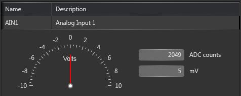
Limits
In the semicircle graphs, it may be observed the voltage working range.
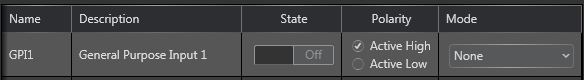
Digital Inputs
All digital inputs are shown here. Their states are shown graphically with a switch animation, with the text "On" or "Off".
| Parameter | Description |
|---|---|
| Polarity | Indicates which signal level turns the state to "On".
|
| Mode | Relates the digital input to a parameter that may be used to control the motion:
|
Analog Outputs
If there is any, analogue outputs are shown graphically and numerically in this panel.
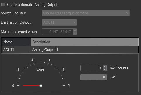
There are two working methods, automatic or manual, that can be configured using the checkbox "Enable automatic Analog Output":
- If it is automatic, the signal value can be taken from an analogue register of the drive board. In this case, the output will vary according to the register it is related to.
- If it is manual, the signal value can be set previously with MotionLab. The value in "DAC counts" determines the output voltage.
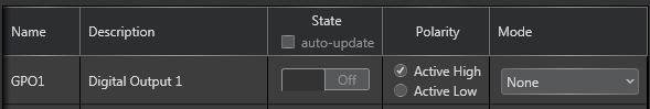
Digital Outputs
All digital outputs appear here. As in digital inputs, their states are shown graphically with a switch animation, with the text "On" or "Off". Moreover, "auto-update" checkbox permits the state to change in real time, useful when monitoring.
| Parameter | Description |
|---|---|
| Polarity | Indicates which signal level comes from the state "On".
|
| Mode | Relates the digital output to a digital parameter from the drive board:
|