MotionLab configuration of Safety related parameters
Purpose of the document
This guide describes the use of MotionLab3 for configuring both motion‑related and safety‑related parameters of a safe drive. MotionLab3 can operate as a Safe Master, eliminating the need to create a separate safety project in TwinCAT, as it internally calculates the SRA CRC value.
To support the configuration process, a real‑world example of a safe drive configuration is provided at each step to offer additional guidance.
Requirements
MotionLab3 version 1.10.0 or later is required.
A Phase 2 safe drive is required, including one of the following products:
Everest S Safe NET
Everest S Safe EVAL
Denali Safe NET
Denali Safe EVAL
A supported feedback combination must be connected to the drive.
Configuration process
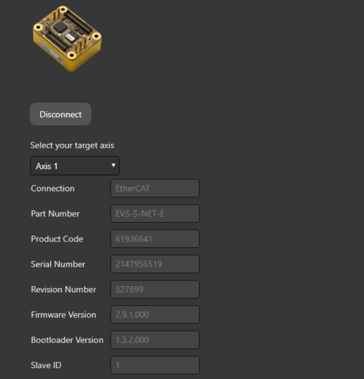
Connect to the drive through MotionLab. It is of good practice to perform a restore all and a power cycle of the drive before starting the configuration process.
Disconnect and connect again to the drive and let’s start passing the Wizard.
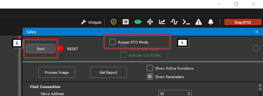
First thing that must be done in order to pass the wizard is the STO bypassing. For the safe drives, STO in not a hardware implementation but a FSoE controlled parameter, it must be bypassed in the Safety tap as to be able to configure the motion related parameters.
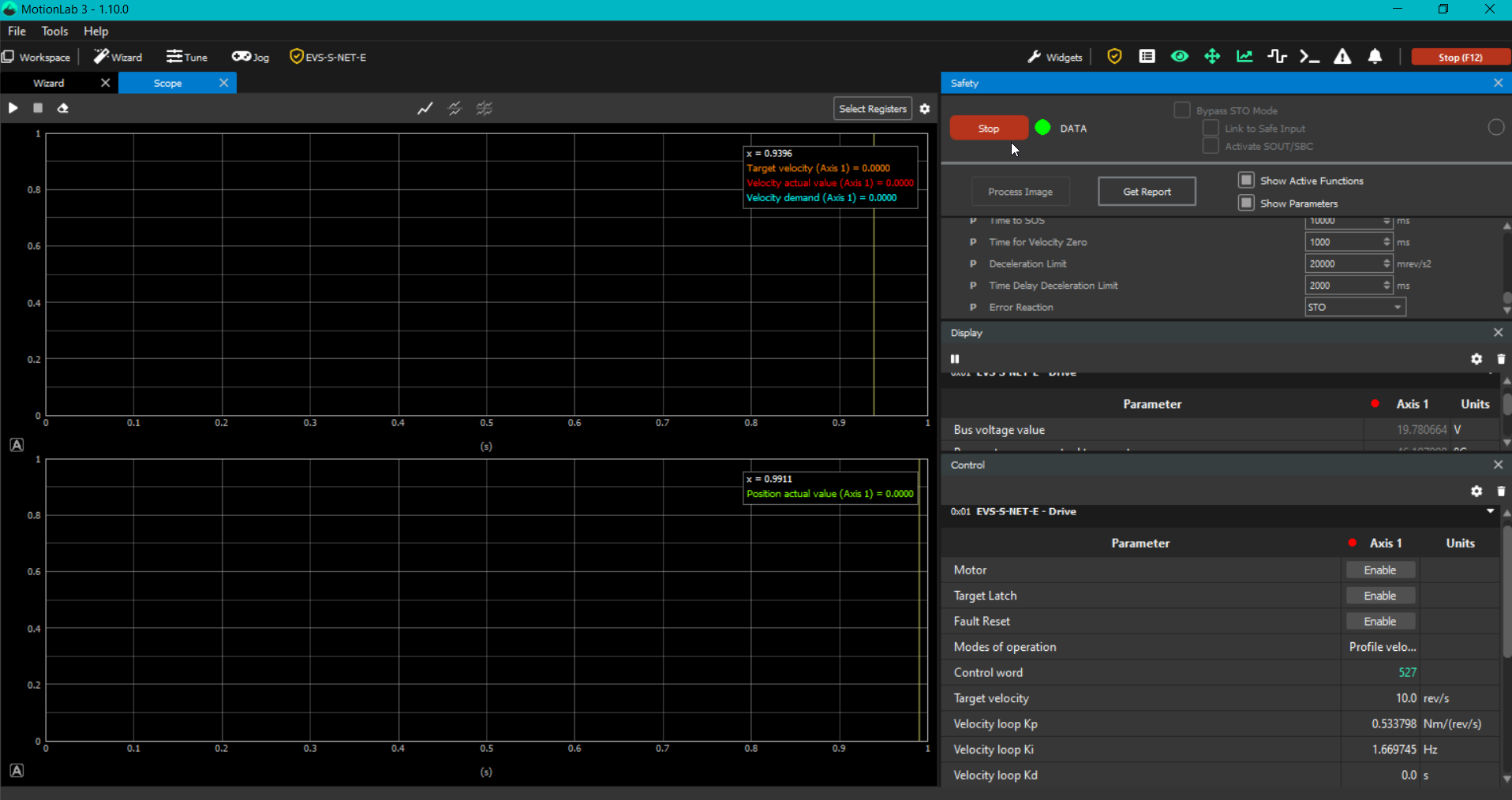
For fast access to the Safety menu click on the yellow icon found at the top right side of the MotionLab window:
First tick the Bypass STO Mode the option and then click on the Start button on its left.
You may now proceed with the configuration wizard by completing all sections, from Limits through Mechanical Tuning. For detailed instructions on drive configuration, please refer to the MotionLab Wizard Manual (that can also be found in the top left corner > Help > Manual).
If a configuration file already exists, disable Bypass STO Mode, then select the Load All option on the drive, load the .xcf file, and finally select the Store All option to apply the configuration. Upon completion, a confirmation message indicating that the store operation was successful will be displayed in the bottom‑right corner of the MotionLab window:
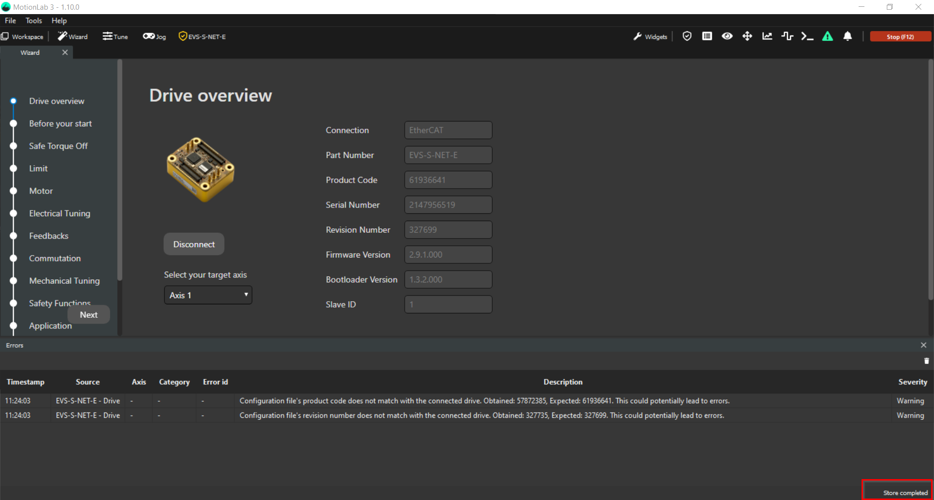
Please ensure that the Store All option is selected after loading the configuration. Failure to do so will result in the loaded parameters being lost after a power cycle.
The errors displayed are coherent as the loaded configuration was extracted from another unsafe drive.
Clarification: “Store all” option can only be performed in the Pre-Operational (Pre-Op) state of the drive (the 2nd LED starting from the right to the left is green and blinking). When the STO is bypassed via MotionLab3, as it a FSoE controlled STO, the mode of operation of the drive is the Operational (Op) state (the 2nd LED starting from the right to the left is fixed green).
If you try to load a configuration with the bypass STO active you will get an error as the drive is designed to be able to change the configurable registers 0x6XXX i 0x2XXX only in Pre-Op state. It is a established drive protection.
Now that you have the configuration stored, you can bypass the STO again as shown in step nr. 4.
With an active STO bypass, let's set up the safety feedback combination in the Feedbacks section of the wizard:
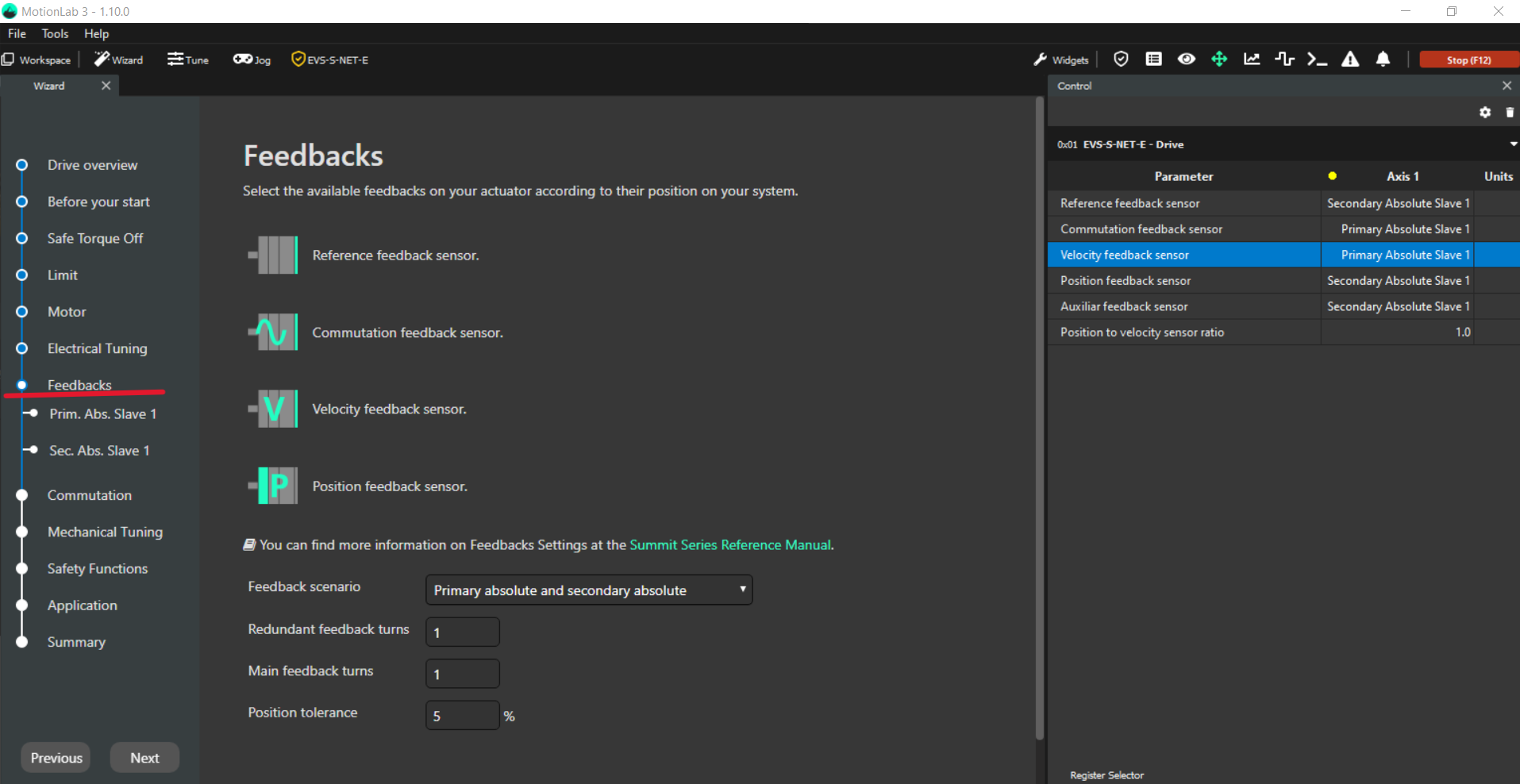
a. When using a safe drive, the implementation of two feedback sensors is required to provide redundancy. Please note that not all feedback combinations are supported for safe drive operation; further details on supported configurations are provided below.
The feedback system may be implemented in applications consisting of either a motor‑only configuration or a motor with a gearbox attachment. In motor‑and‑gearbox systems, the feedback sensor mounted on the motor is referred to as the redundant feedback, while the sensor connected to the gearbox output is designated as the main feedback.
In motor‑only configurations, both the main and redundant feedback sensors monitor the same motor shaft to ensure the required level of redundancy.
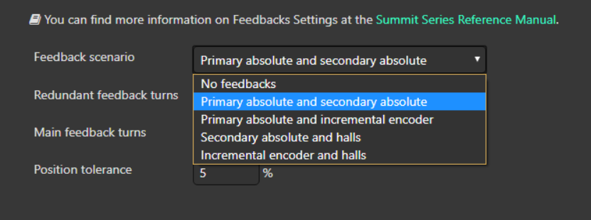
As shown in the MotionLab Feedback scenario selection menu, the available options follow a consistent naming convention in which the main feedback is listed first, followed by the redundant feedback (format: main_feedback and redundant_feedback).
The supported feedback combinations for the safe drives are:
Feedback Combinations | ||
|---|---|---|
Combination code → MotionLab selection | Main feedback sensor | Redundant feedback sensor |
FBK0 → No feedback | - | - |
FBK1 → Primary absolute and secondary absolute | BISS-C BP3 - Port 1 | BISS-C BP3 - Port 2 |
FBK2 → Primary absolute and incremental encoder | BISS-C BP3 - Port 1 | QEI |
FBK3 → Secondary absolute and halls | BISS-C BP3 - Port 2 | Digital Halls |
FBK4 → Incremental encoder and halls | QEI | Digital Halls |
In the following illustrated example, no gearbox is attached to the motor, and two BiSS‑C absolute encoders are selected as the feedback sensors:
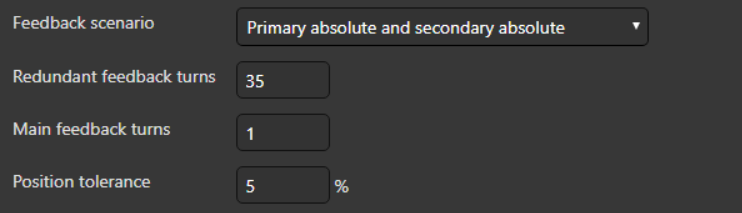
In applications where a gearbox is used (for example, with a 35:1 gear ratio), the configuration is as follows:
MotionLab parameters | Meaning |
|---|---|
Redundant feedback turns | Motor output turns |
Main feedback turns | Gearbox output turns |
Position tolerance | The allowable error between the motor turns and the gearbox turns |
b. Once both feedback sensors have been correctly configured and successfully tested (step 5), the parameters must be transferred to the safety configuration by selecting the Copy to Safety Parameters option:
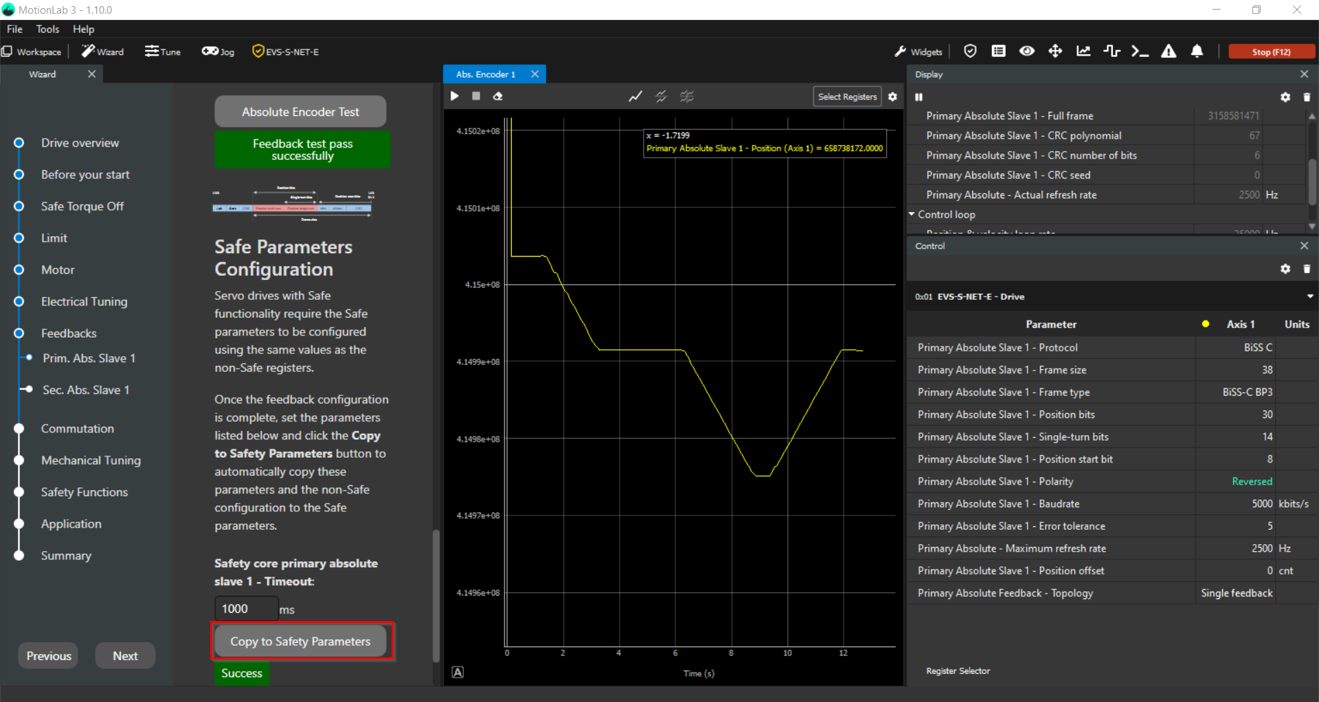
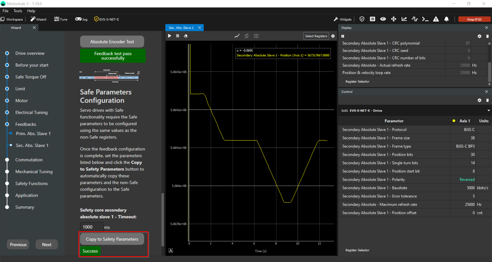
Clarification: Selecting Copy to Safety Parameters does not immediately store the values in the safety core. This action only saves the parameters within MotionLab.
Once Bypass STO Mode is disabled, the parameters are then transferred to the safety core. To ensure the configuration is permanently applied, a Store All operation is also required.
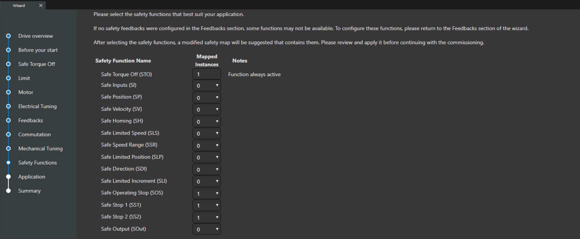
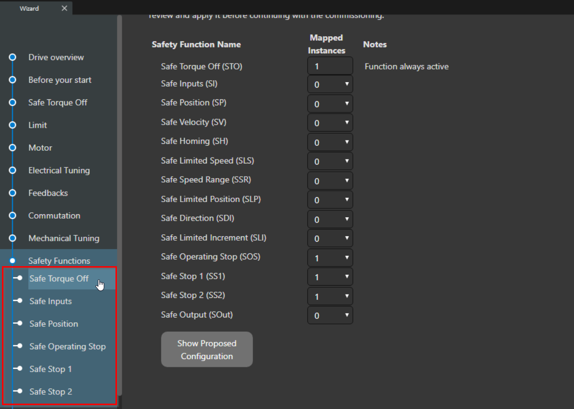
The next step is to select the required safety functions and define the corresponding number of instances for each function.:
Once the selections are complete, disable Bypass STO Mode and select the now available Show Proposed Configuration.
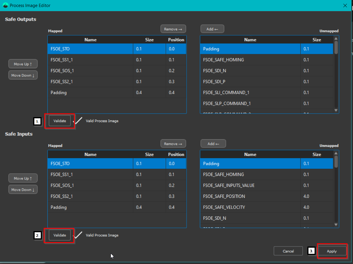
Review and validate the configured safety functions, including the associated safe inputs and safe outputs, to ensure the configuration meets the safety application requirements:
Once the safe inputs and safe outputs have been validated, the configuration of the function‑specific parameters can be performed from two different locations within MotionLab
The first and most commonly used method is via the Safety Functions section located on the left‑hand side of the MotionLab window. Within each individual safety function section, a graphical representation is provided to guide the user through the configuration process:
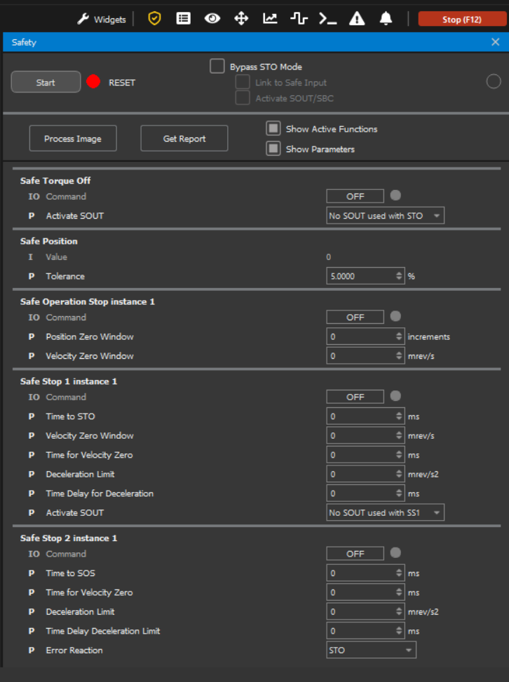
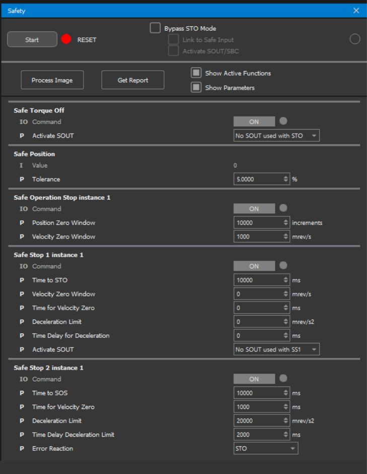
The second method for editing parameters related to the safety functions is also accessible via the Safety menu on the left‑hand side of the MotionLab window. To facilitate identification of the currently configured safety functions, enable the Show Active Functions and Show Parameters options:
Detailed information on the purpose, usage, and associated registers of each parameter is provided in the Safety Functions Configuration Guide (coming soon).
These parameters are set while the drive is in Pre-Operational state. To ensure the configuration is permanently applied, a Store All operation is also required.
The Safety Panel represents the perspective of the FSoE Master. Please note that the ON and OFF indications follow the standard FSoE Master convention, which may be reversed compared to the internal activation and deactivation logic used by certain safety functions within the drive.
For the safety functions STO, SI, SP, SV, SH, SLS, SSR, SLP, SLI, SOS, SS1 and SS2 the ON/OFF of the Safety menu mean:
Safety tab option per function | FSoE Master | Safety function status reported from drive |
|---|---|---|
OFF | The FSoE Master commands the activation of a specific safety function when the corresponding control signal is set to 0. | The safety function command within the drive is initially by default at 0. This indicates that the safety function has not been activated yet. Conversely, the safety function command within the drive transitions to 1, indicating that the safety function has been successfully enabled and within the established limits. For STO and SI don’t have established limits. The safety function command within the drive will transition to 0 if the operation is outside the defined limits and transitioned to a configured (in some cases) Safe State. This indicates that the safety function has been deactivated. |
ON | The FSoE Master commands the deactivation of a specific safety function when the corresponding control signal is set to 1. | The safety function command within the drive will transition to 0, indicating that the safety function has been deactivated. |
For the safety function SOUT the ON/OFF of the Safety menu mean:
Safety tab option per function | FSoE Master | Safety output status reported from drive |
|---|---|---|
OFF | The FSoE Master commands the activation of the safe output with the corresponding control signal is set to 0. | The safe output command within the drive transitions to 0 indicating that the safe output has been activated. |
ON | The FSoE Master commands the deactivation of the safe output with the corresponding control signal is set to 1. | The safe output command within the drive transitions to 1 indicating that the safe output has been deactivated. |
SOUT ONLY FOR EVS-SAFE
For the safety option SDI the ON/OFF of the Safety menu mean:
Safety tab option per function | FSoE Master | Safety function status reported from drive |
|---|---|---|
OFF | The FSoE Master disables movement in the specified direction (positive/negative) when the corresponding control signal is set to 0. | If the motor is not moving in the specified direction, the drive reports a 0. If the motor is moving in the specified direction, the drive reports a 1. While the motor is moving in the specified direction (status reported is 1), if the SDI position zero window is exceeded, the status of the safety function transitions to 0 and the Safe State is activated (only STO). |
ON | The FSoE Master enables movement in the specified direction (positive/negative) when the corresponding control signal is set to 1. | Independent of the motor movement, the drive reports a 0. |
Make sure to disable or enable the safety functions through MotionLab using the criteria mentioned above. Click the Start button to enable the MotionLab FSoE Master and the drive transitions to the operational state.
Using the following workspace ( TestSafeFunctions.xws ) you can try the safety functions. Enable/disable them easily using the Safety menu: