How can I optimize the EtherCAT latency in my drive?
Maximum update rate of the drive up to 250us (4 kHz) keeps the latency of 2-3 cycles. One requirement to do that is using PWM higher or equal to 50 kHz and PDO size up to 11 bytes. Please see the EtherCAT specifications for your specific drive. For EVS-XCR-E, it can be seen here: EtherCAT specifications.
Additional factors to be taken into account are:
Our PDO mapping can be changed dynamically, so the copy and calculation time depends on the number of registers and the register itself.
In order to get the maximum efficiency please consider:
Internal drive update rate: Operation
If the power stage is running at 20 kHz, all the control loops are working at that frequency. That means that all the "variables" are being updated 5 times per EtherCAT cycle (4 kHz).
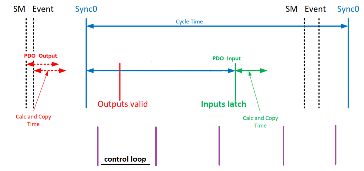
The optimal latency (1 cycle) is achieved if there are two internal loop cycles between the data is available for the inner loops (outputs valid in the below diagram) and the outputs are copied into the EtherCAT buffer (inputs latch in the below diagram). However, if there are too many registers mapped this 1 cycle latency is not reachable.
This should be done experimentally once the PDOs for the application are selected.

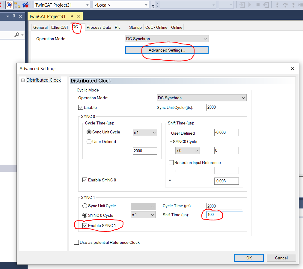
Enabling the Sync1 signal. Sync1 signal indicates the inputs latch from the below diagram. This allows the control over Sync0 and Sync1 so the time between them can be maximized. The optimal shift time must be estimated experimentally.
The Sync1 shift time can be configured through the ESC registers. Please refer to the Beckhoff guide if you are using TwinCAT: Section II - Register Description (beckhoff.com) (Section 2.50.2).

For further detail on the Sync1 use, please refer to the following page: Application Note ET9300 (beckhoff.com).
