Communications
The Titan Go Servo Drive provides the following network communication interfaces for configuration and operation:
All the interfaces can be used to connect the Titan Go with Ingenia MotionLab suite or a custom built application with the supplied controller libraries. With the objective of configure and diagnostic CAN communication, CANopen and another communication interface can be used simultaneously.
USB interface
Titan Go Servo Drive supports Universal Serial Bus (USB), a standard interface for connecting peripheral devices to a host computer. The USB interface is isolated from the rest of the drive to provide extra ruggedness against noisy environments. The following table shows main USB interface specifications:
Specification | Details |
|---|---|
USB version | USB 2.0 (full speed) |
Data rate | Up to 12 Mbps |
Recommended maximum cable length | 1 meters (3 feet) |
| Isolation | 2.5 kVRMS |
USB application
USB interface is recommended for configuration purposes. For noisy environments, CANopen or RS485 interfaces are strongly recommended.
USB wiring recommendations
Although USB is a widespread communication standard it has some disadvantages when operating in noisy environments. Following are some wiring recommendations.
- Use shielded cable with the shield connected to PC end. Shield of mini USB connector is connected on Titan Go, but it is isolated from the rest of the drive.
- Do not rely on an earthed PC to provide the Titan Go Servo Drive earth connection. The drive must be earthed through a separate circuit.
- Avoid creating ground loops by using isolated power supplies.
- Make sure to separate USB shield from power protective earth. If using panel connectors, avoid metal versions where the USB shield is in contact with the metal enclosure, this may seriously reduce USB performance by coupling power noise to the weak communications ground.
- Shortest cables are always preferred.
RS485 interface
Titan Go Servo Drive supports full duplex RS-485. This means that independent differential lines are used for TX and RX, which cannot be connected together. Full-duplex RS485 is fully compatible with RS422 communication.
Multi-point connection
Titan Go Servo Drive RS485 interface is not intended for bus operation, since there is no collision prevention protocol implemented. However, multiple drives can be connected to the same master using daisy chain connection.
Multiple drive connection with daisy chain must be configured using Ingenia MotionLab suite. For allowing multi-point communication each servo drive must be allocated a unique node ID, and daisy chain option must be enabled. Please, see UART configuration section in E-Core documentation for further information.
Main specifications of Titan Go RS485 interface are shown in the next table:
Specification | Details |
|---|---|
| Interface | Full duplex. Isolated (GND shared with CAN). Self-supplied (no need for external supply) |
| Communication distance | Up to 1200 m |
| Baud rate | 128 kbps to 460 kbps |
Daisy chain | Supported |
| Termination resistor | 120 Ω termination resistor on RX channel |
Next figure illustrates how to connect Titan Go Servo Drive with a host in a point to point configuration.
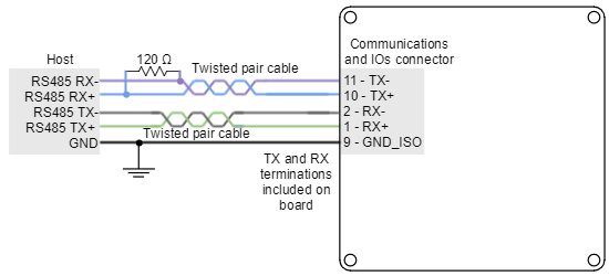
Termination resistor
The use of termination resistors at the RX side of each differential pair (120 Ω between RX+ and RX- of both host and slave) is essential for correct operation of the RS485 communication. For long cable distances (> 10 m) a termination in the TX side is also recommended.
Titan Go Servo Drive includes TX and RX termination resistors on board. They can be activated/deactivated with the switches available near the connector. Another 120 Ω termination resistor should be placed at the end of Titan Go TX line (RX of the host). Suggested termination resistor: Xicon 271-120-RC.
Multi-point connection using daisy chain
Daisy chain connection is a multi-point network topology based on connecting multiple terminals in a ring. The wiring consists on connecting the TX terminals of each device to the RX terminals of the next device. An example of daisy chain wiring of multiple Titan Go is shown in the next figure.
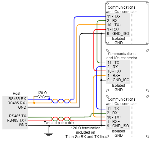
Termination resistor for daisy chain
In daisy chain connection, termination resistors are required in each link. For short distances, a 120 Ω termination resistor in the RX side is required. For long distances (> 10 m) it is required in RX and TX sides.
Titan Go Servo Drive includes TX and RX termination resistors on board. They can be activated/deactivated with the switches available near the connector.

CANopen interface
Titan Go Servo Drive provides access to the CANopen interface, a multi-terminal communication protocol based on CAN (Controller Area Network) bus. Titan Go CAN interface is isolated, and self-supplied. Main physical specifications are shown in the next table:
Specification | Details |
|---|---|
| Interface | Isolated (GND shared with RS-485). Self-supplied (no need for external supply) |
Baud rate | From 125 kbps to 1 Mbps (default value) |
Maximum number of nodes | 64 |
Common mode voltage | Up to 36 V |
| Termination resistor | 120 Ω on board (externally connect CAN_TERM to CAN_L to enable) |
Drive ID
When installing CANopen communication, ensure that each servo drive is allocated a unique ID. Otherwise, CANopen network may hang.
An example of CAN wiring is shown in the next figure.
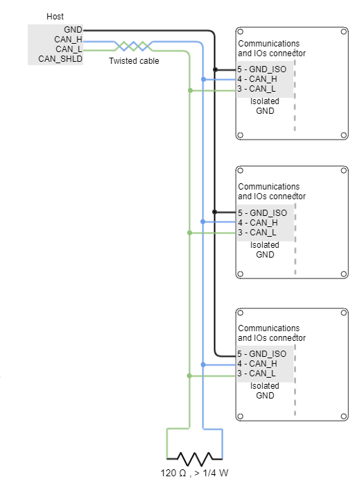
Termination resistor
The use of bus termination resistors (120 Ω between CAN_L and CAN_H), one at each end of the bus, is essential for correct operation of the CAN bus. Even with only one Titan Go connected, mount the termination resistor to ensure CAN bus operation. Do not use wirewound resistors, which are inductive.
Titan Go Servo Drive includes a termination resistor on board. It can be activated/deactivated with the switch available near the connector.
CAN interface for PC
The Ingenia MotionLab suite is able to communicate with the Titan Go Servo Drive through CANopen interface. For this purpose, a CAN transceiver for PC is required. Motion Lab is compatible with the following CAN transceivers: Kvaser, Peak-System, IXXAT, Vector and Lawicel.
Some recommended CAN transceivers are shown below:
| Manufacturer | Part Number | Image | Description |
|---|---|---|---|
| Peak-system | PCAN-USB opto-decoupled (IPEH-002022) |  |
|
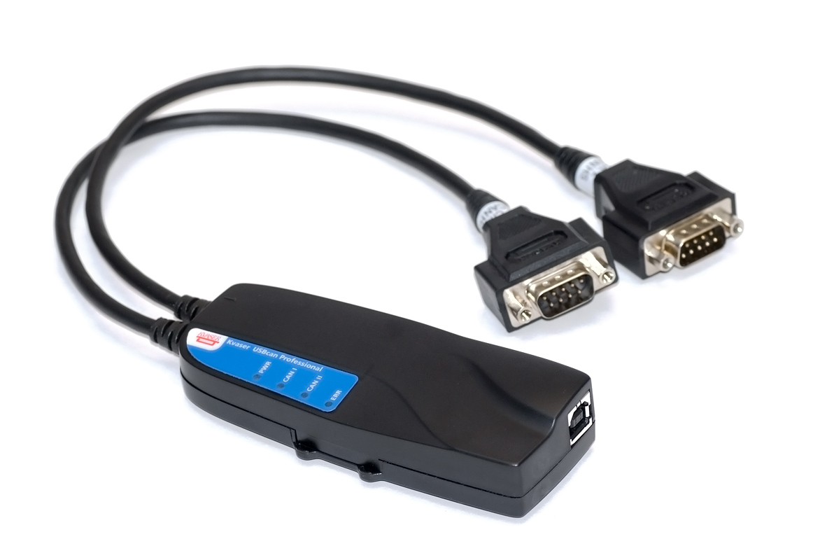
| Kvaser | USBcan Pro 2xHS v2 |
|
|
| IXXAT | USB-to-CAN V2 Professional |  |
|
| Vector Informatik | VN1630 | 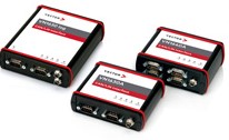 |
|
CAN wiring recommendations
- Build CAN network using cables with 2-pairs of twisted wires (2 wires/pair) as follows: one pair for CAN_H with CAN_L and the other pair for CAN_V+ with CAN_GND.
- Cable impedance must be of 105 to 135 Ω (120 Ω typical) and a capacitance below 30 pF/meter.
- Whenever possible, use bus links between the CAN nodes. Avoid using stubs (a "T" connection, where a derivation is taken from the main bus). If stubs cannot be avoided keep them as short as possible. For maximum speed (1 Mbps), use a stub length lower than 0.3 meters.
- For a total CAN bus length over 40 meters, it is mandatory to use shielded twisted cables. Connect the cable shield to protective earth at both ends. Ensure that the cable shield is connected to the connector shield, as connection to host protective earth is usually soldered inside the connector.