Dimensions and assembly
The Titan Go Servo Drive have a 206 mm x 172 mm footprint, 55 mm height and 4 x Ø 9 mm holes for M8 screws mounting.
Thermal dissipation required
To reach its power specifications, Titan Go must be mounted over a heatsink, and a thermal interface material must be placed and compressed in between to ensure a good contact. See below 👇.
Titan Go Dimensions
Following are shown the Titan GO dimensions. For further details download the 3D model.
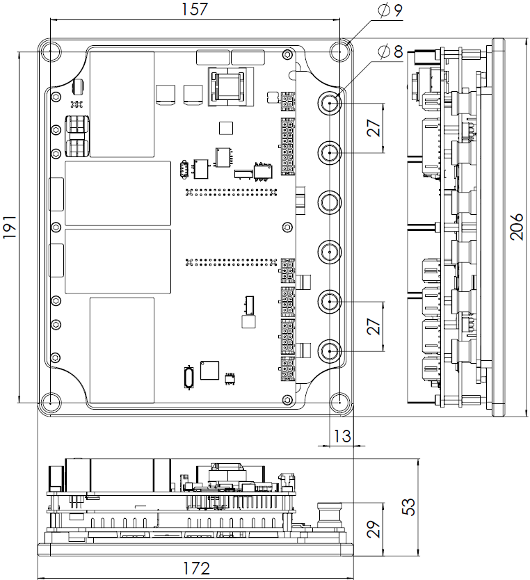
All dimensions are in mm. All tolerances ≤ ±0.2 mm.
Assembly Instructions
The assembly of the plate to a cooling surface is essential to achieve desired performance. Due to the dimensions of the plate, it is essential that the thermal pad is thick and soft enough to compensate the flexing during assembly. Thermal grease is not recommended since an imperfect application will leave air gaps wich result in poor heat transfer. Next are some thermal interface materials suitable for the Titan.
Heatsinks or cooling plates
In order to choose the cooling needs of the Titan, please see the thermal calculations in Product Description page.
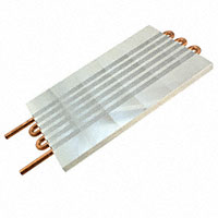
Given the power ratings of the Titan, typically passive cooling heatsinks will not be enough for continouous operation. Forced air or water cooling solutions are suggested. See some examples next:
| Manufacturer | Type | Part Number | Thermal resistance | Dimensions | Image |
|---|---|---|---|---|---|
Wakefield-Vette | Liquid cooling plate with exposed copper | 120459 | 0.007°C/W at 1.4 GPM | 381.0 mm x 127.0 mm x 15.2 mm (excluding heat exchanger and pump) |
|
| Fischer Elektronik | Heatsink with cooling fan at 24V | LA 11 200 24 | 0.055°C/W | 240 mm x 200 mm x 83 mm |
|

You can have the highest performance cooling plate and not be capable of cooling the Titan if the assembly is incorrect!
Please use appropriate thermal interface materials and follow the assembly instructions to achieve an excellent heat transfer. See below 👇.
Thermal interface material
Thermal interface materials for a cooling plate with a big surface should be tacky and soft to prevent the formation of air bubbles. Also thickness should be enough to compensate for the flexion of the plate while being compressed, 0.5 mm is typically enough for this purpose.
Please note that thin "high performance" materials that look promising on the datasheet may end up with poor heat transfer. With thin materials the pressure is only applied near the screws and air bubbles are formed, decreasing the heat transfer dramatically.
| Manufacturer | Part Number and description | Thickness before compression | Thermal conductivity | Estimated thermal resistance plate to heatsink |
|---|---|---|---|---|
| Laird Technologies | A15896-02 TFLEX 720 9X9" | 0.50 mm | 5.0 W/m·K | 0.003 K/W |
| Laird Technologies | A15896-04 TFLEX 740 9X9 | 1.00 mm | 5.0 W/m·K | 0.005 K/W |
| Bergquist | GPHC5.0-0.020-02-0816 | 0.51 mm | 5.0 W/m·K | 0.003 K/W |
| Bergquist | GPHC5.0-0.040-02-0816 | 1.02 mm | 5.0 W/m·K | 0.005 K/W |
| t-Global Technology | H48-6A-320-320-0.5-1A | 0.50 mm | 4.0 W/m·K | 0.004 K/W |
| t-Global Technology | H48-6A-320-320-1.0-1A Adhesive one side | 1.02 mm | 4.0 W/m·K | 0.006 K/W |
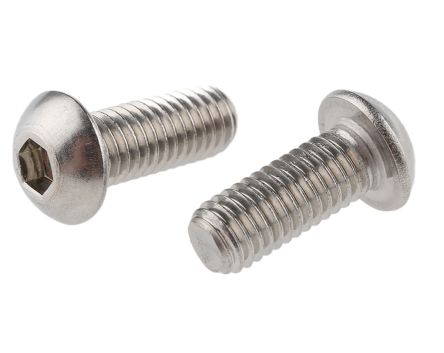
Screw assembly
Screw the plate evenly. Apply a torque that guarantees pressure on all the surface and does not bend the aluminum plate. Recommended screw size is M8. Use stainless steel good quality screws. The maximum screw torque is 9 Nm. Higher torque will not result in better heat transfer as the plate would bend and pressure would not be well applied.
Spring washers are a must in order to guarantee long term pressure.
| M8 screw | |
|---|---|
| Description | M8 allen screw, 20 mm length |
| Image |
|
| Part number | RS-Pro 232-8344 |
| Distributor codes | RS 232-8344 |
| Crinkle washer | |
| Description | M8 stainless steel crinkle washer |
| Image |
|
| Part number | Duratool D00829 |
| Distributor codes | Farnell 1614006 |