Safe Torque Off (STO)
The STO is a hardware safety system that prevents motor torque in an emergency event. When STO is activated, the power stage is disabled automatically (no mater what control or firmware does), and the motor shaft will slow down until it stops under its own inertia and frictional forces.
Do not leave STO unconnected
If STO is not used, both inputs STO1 and STO2 must be enabled. Otherwise it will be impossible to apply torque to the motor.
Tip: In order to enable the inputs it is suggested to connect STO_COMMON to GND of connector P1 and connect both STO1 and STO2 to 24V_OUT of connector P1.
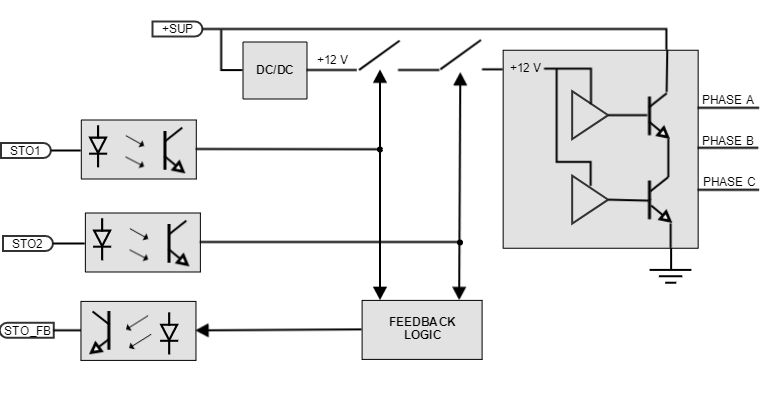
The Titan Go STO works with negative logic, deactivating the power stage by default. In order to activate the power stage, and therefore allow the motor operation, two differential inputs must energized. These inputs activate two optocouplers that enable the Titan Go power stage operation. On the contrary, if the STO inputs are not energized, the transistors of the power stage are turned off and a STO fault is notified. During this state, no torque will be applied to the motor no matter configuration, or state of a command source. This will slow down the motor shaft until it stops under its own inertia and frictional forces. This input should not be confused with a digital input configured as enable input, because enable input is firmware controlled and does not guarantee intrinsic safety as it can be reconfigured by a user.
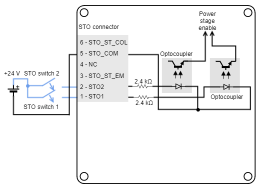
The following diagram shows a simplified schematic of the STO circuit.
The Titan Go STO have been designed to be compliant with Safety Integrity Level 3 (SIL 3) according to IEC 61800-5-2. In order to fulfill the requirements, the STO reliability has been increased by means of the following charateristics:
- Two fully independent STO channels
- STO Feedback output for external diagnostics
- Detection of abnormal STO operation
Fully independent STO channels
The power stage logic is supplied by two cascaded MOSFET transistors. Each transistor is activated by an independent isolated STO input. The design guarantees that a single failure will not accidentally activate the power stage.
STO firmware notification
An STO stop is notified to the control DSP and creates a fault that can be read externally, however its performance is totally independent from control or firmware. When the STO is not connected it is virtually impossible to apply power to the drive.
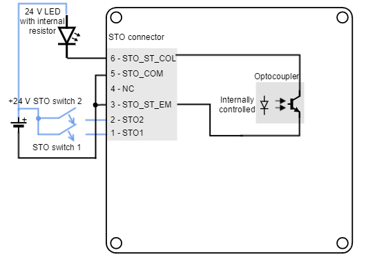
STO inputs have an input voltage of +24 V. Next figure shows how to connect the STO inputs with an external power supply.
STO status feedback output
The STO also includes a status feedback output. It is automatically controlled by the internal circuits, and the output is normally active, providing a closed contact. When one of the STO inputs becomes de-energized (low-level), the STO_ST becomes low-state too.
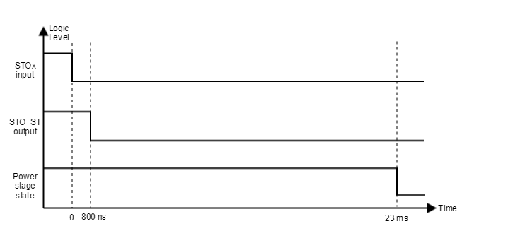
The objective of the STO_ST is to allow external diagnostics of the STO circuit, allowing an increase of the system reliability. A common-practice in the diagnostics is to delay the stop of the power stage from the deactivation of the STO_FB and from the deactivation of the STO inputs. This way, short pulses can be applied for testing the STO circuit without stopping the system operation.
The following figure shows the timings corresponding to the STO:
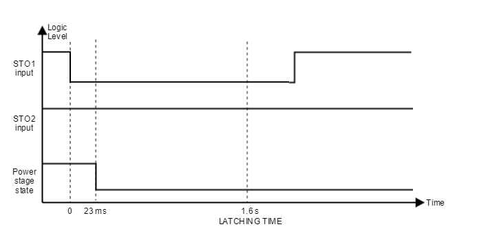
STO abnormal operation
Abnormal operation of the STO is when only one of the channels is energised. In case that only one channel is energised for more than 1.6 s, a dangerous failure in the system is considered and the STO is activated in latching mode. The fault cannot be reset until a supply reset is performed.
The following figure shows an example of the STO abnormal operation.
The following table shows a sumary of the STO performance.
| Mode | Status | STO1 input | STO2 input | Power stage state | STO_FB | Drive function |
|---|---|---|---|---|---|---|
| Normal operation | STO ACTIVE | 0 | 0 | Disabled | 0 | Drive cannot start or provide power to the motor. STO trip reported to the DSP and to STO_FB. This is intended safe torque off with dual channel operation. |
STO INACTIVE | 1 | 1 | Enabled | 1 | Drive is enabled to run under firmware control. The drive can supply power to the motor. | |
| Diagnostic | STO ACTIVE PULSE (1 ms < t < 23 ms) | x | 0 | Enabled | 0 | A short STO ACTIVE ("0") pulse does not stop the motor operation. However, it activates the STO FEEDBACK. It can be used for performing system diagnosis and increasing system reliability. |
| STO ACTIVE PULSE (1 ms < t < 23 ms) | 0 | x | Enabled | 0 | ||
| Abnormal operation | Abnormal STO ACTIVE | 0 | 1 | Disabled | 0 | Drive cannot start or provide power to the motor. STO trip reported to MCU. If this persists for > 2.3 s the STO will lock in FAULT state. To reset this fault a power cycle is needed. |
| Abnormal STO ACTIVE | 1 | 0 | Disabled | 0 | ||
| STO FAULT | x | x | Disabled (latched) | AND (STO1, STO2) | After > 2.3 s of abnormal STO active the driver will stay latched in this state untill power cycle. |
Finally an example to use the STO_ST to drive a signalling LED (transistor optocoupler tolerant up to 80 V and 50 mA):