Secondary SSI
SSI
SSI is also a serial protocol but does not define a specific frame. Every feedback product has its own protocol/frame over SSI. These frames can contain manufacturer-specific special bits. Some of these frame types are supported, allowing decoding special bits in some cases. An example of a manufacturer-specific SSI frame is the "Zettlex - SSI1" frame type, which contains a "Position valid bit" that can be used to detect transmission/encoder errors
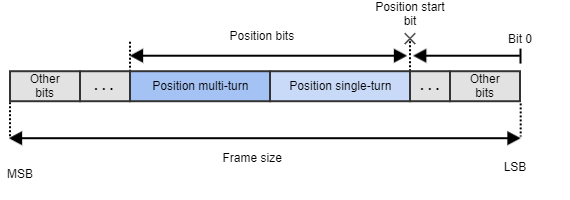
An SSI frame would have the following structure
Serial Synchronous 1
Serial Synchronous 1 is a protocol created to communicate with devices that implement a non-standard SSI protocol used by some manufactures. It follows the structure of the SSI protocol described above but the clock signal is inverted respect to the standard: the signal is in low state when inactive and data is transmitted on falling edges.
Configuration for SPI Drives
A set of parameters are available to the user to adapt the absolute interface to the different supported protocols:
Protocol. Indicates if the encoder protocol is SSI, BiSS-C or Serial Synchronous 1
Frame size. Indicates the total number of bits of the frame. These include position bits, special bits, warning, error and CRC bits, etc.
0x378 - Secondary Absolute Slave 1 - Frame size
ACK, START and CDS bits should not be included in this parameter
Please be aware that the maximum frame size depends on the Actual refresh rate and the Baudrate. Larger frame sizes (over 40 bits) may require higher baudrates.
Error tolerance. The drive is able to detect an incorrect frame (for example by reading the position valid flag of the SSI1 frame type, or by parsing the CRC and error bits in the BiSS-C frame). If an incorrect frame is detected, it is ignored and the drive keeps the last read position as the current position. However, if too many followed errors are detected, the drive generates a fault and stops the operation. This register specifies the number of errors accepted before generating the fault.
0x379 - Secondary Absolute Slave 1 - Error tolerance
Setting a 0 value will ignore any error from the encoder.
Wait cycles. Control loops might work at high rates, and the specified minimum period between BiSS-C / SSI frames might be higher than the loop update rate. In this case, the drive must wait for some control loops before requesting new data. This register specifies how many position loop cycles the drive will wait before requesting new encoder data.
0x37A - DEPRECATED - Secondary Absolute Slave 1 - Wait cycles
This parameter is deprecated in FW version 2.4.0
Polarity. Indicates the direction of rotation of the encoder. 0 value applies standard polarity (read directly from the feedback) and a value different than 0 reverses the polarity.
Frame type. Indicates the format of the received frame. This parameter allows parsing frames in a specific way. For example, the BiSS-C BP3 profile frame type will assume there are CRC, error and warning bits and will use them to detect errors in the frame
0x37C - Secondary Absolute Slave 1 - Frame type
For unsupported frame types, use raw or raw gray modes. These modes allow reading the position from any frame type without processing special bits such as CRC or error flags.
Note
Frame type 3 implements the BiSS-C BP3 profile. By selecting this frame type, the first 8 bits will automatically be used for CRC and error checking, since a BP3 BiSS-C frame is assumed. More information about this profile can be found here
With BiSS-C BP3 type selected, frames with errors will be discarded.
Position bits. Indicates the number of bits used for position readings.
0x37D - Secondary Absolute Slave 1 - Position bits
Note
The device calculates its own multi-turn data to allow covering the whole position variable range. Use position range configuration if the systems needs to work only in the absolute encoder range.
Single-turn bits. Indicates the number of position bits that represent single-turn information.
0x37E - Secondary Absolute Slave 1 - Single-turn bits
This information is used by the drive to compute the angle commutation properly. For multi-turn absolute encoders, this information gives the reference of 1 mechanical revolution to the drive.
For single-turn absolute encoders, position bits must be equal to single-turn bits.
Note
Writing the following parameters will cause the software multi-turn (multi-turn part calculated by the driver) to be reset to 0: Frame size, Polarity, Frame type, Position bits, Single-turn bits, Position start bit and Position offset
Position start bit. Defines how many bits the position information is displaced from the LSB in the serial absolute feedback frame.
Position offset. Adds an offset to the read encoder position (after polarity has been applied). Negative values on this parameter shift the overall position in the negative direction and positive values shift it to the positive direction
Position. Shows the encoder position value taking into account the polarity, position offset and (if available) software multi-turn.
Full frame. Contains last received frame including special bits, for debugging purposes
Maximum refresh rate. This parameter specifies the maximum refresh rate allowed for the absolute encoder connected. The driver will send frames to the encoder at a rate equal or lower than the value introduced.
0x399 - Secondary Absolute - Maximum refresh rate
This parameter exists after FW version 2.4.0
Actual refresh rate. This parameter shows the refresh rate at which absolute encoder frames are being sent. It will be a multiple of the position loop rate and will never exceed the 'Maximum refresh rate'. The driver can lower the refresh rate if the frame duration is too long.
0x39B - Secondary Absolute - Actual refresh rate
This parameter exists after FW version 2.4.0
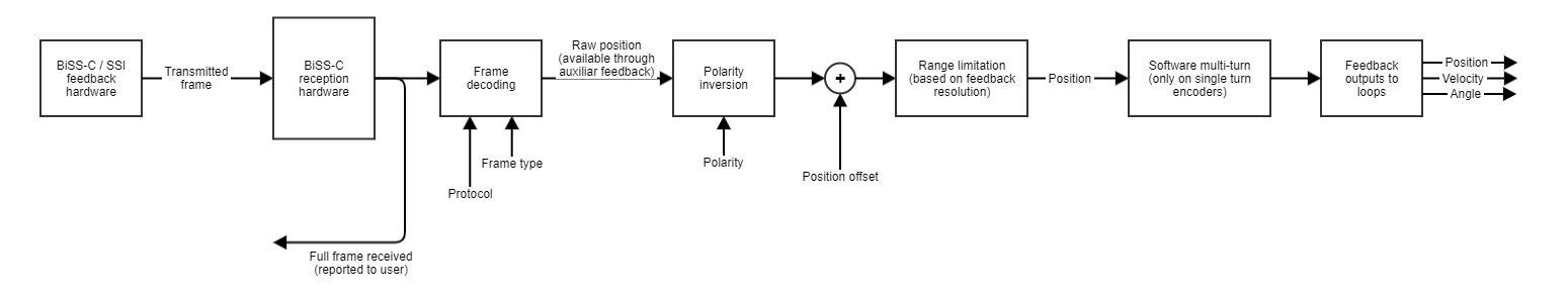
How the data is parsed