Protective Earth
Connection of Capitan XCR Servo Drive and motor housing to Protective Earth (PE) is required for safety and Electromagnetic Compatibility (EMC) reasons. Electrical faults can electrically charge the housing of the motor or cabinet, increasing the risk of electrical shocks. A proper connection to PE derives the charge to Earth, activating the installation safety systems (differential protections) and protecting the users. Please see this technical note to understand why this is important: Electromagnetic Interference Issues With Servo Drive Systems.
Reducing EMI susceptibility
Connecting the drive PE terminals and cold plate screws to your system Earth and to the motor housing solves many noise and EMC problems. The enclosure of the drive and PE terminals are decoupled to power ground (supply negative, GND_P) through two 1 nF capacitors. This creates a low impedance preferential path for coupled common-mode noises that otherwise would be coupled to sensitive electronics like the encoders.
Capitan XCR Servo Drive provides the following Protective Earth connection points, which are internally connected and decoupled to power ground:
PE terminal in the motor connector P2 pin 4.
Driver housing
Threaded M2.5 assembly holes
Pin 20 of feedback connector J1
Pin 2 of Inputs/outputs connector J2
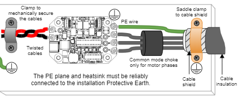
The protective earthing conductor must have an area equal or superior to the power cables and always no less than 2.5 mm². Respect the green-yellow color code for PE. Connections must always be done using non-corrosive bonding points. A diagram of the recommended Protective Earth wiring is shown following.
Earth plane reference
While some systems will not have a "real Earth" connection, use your machine chassis, the metallic structure of the device or a good grounding conductive plane as your reference earth.
Some considerations for a proper earth connection are detailed next:
Connecting PE to GND_P near the power supply can provide an advantage for EMC and electrical safety by keeping a low voltage. Dis can only be done when the drive is powered with an isolated power supply or battery. This action, however sometimes can create unwanted effects such as added common mode noise or electrical safety issues depending on the whole installation layout.
Switching noise by the phases is coupled to earth through the housing of the motor. This high-frequency noise creates a common mode current loop between drive and motor. Although the motor housing is connected to earth through the system chassis, its electrical connection may have a relatively high impedance and present a big loop. For this reason, is essential to reduce the common-mode current return path impedance and its loop area.
To reduce the return path impedance the motor frame should be directly wired to drive PE terminals or enclosure.
PE wiring should be as close as possible to motor power cables.
In order to avoid ground loops, it is a good practice to have a central earth connection point (or bus) for all the electronics of the same bench. If multiple drives are supplied from the same power supply or supply PE to drive PE connection is not practical (not enough connection terminals) connect all PE terminals in a central connection bus.
Whenever possible, mount the drive on a metallic conductive surface connected to earth like the heatsink. Use good quality screws with spring washers that will not oxidize or lose conductivity during the expected lifetime.
For achieving low impedance connections, use wires that are short, thick, multi-strand. PE wire section should be the same as power supply cables. Always minimize PE connection length.
For best EMC performance Capitan XCR should be mounted physically close to the actuator or inside the enclosure.
In case the Capitan XCR is not integrated on the motor or actuator, use shielded cables with isolating jacket, connecting the shield to PE with a cable clamp to the PE plane. The priorities are:
Shield the motor cables, which are the main high-frequency noise source.
Shield the feedback signals, which are sensitive signals usually coming from the motor housing. Connect the shield to one end (drive) to avoid ground loops.
Shield I/O signals and communication cables.
The clamp has to be selected according to the shielded cable diameter, ensuring good support and connection between the cable shield and the clamp. The clamp also offers a mechanical securing of the soldered wires. Following examples are only suggested for a conceptual purpose:
Description | Part number |
|---|---|
Cable Clamp, P-Type Silver Fastener 0.187" (4.75 mm) | Keystone Electronics 8100 |
Cable Clamp, Saddle Type Stainless Steel 20 mm | RS Pro 471-1300 |