
|
Index |
Sub Index |
Name |
Data Type |
Acc. |
Pdo Map. |
NVM |
Value range |
Default value |
Units |
|---|---|---|---|---|---|---|---|---|---|
|
0x2600 |
0x01 |
Current phase A |
INT16 |
RO |
Yes |
No |
ADC range (see below) |
0 |
ADC counts |
|
0x2600 |
0x02 |
Current phase B |
INT16 |
RO |
Yes |
No |
ADC range (see below) |
0 |
ADC counts |
|
0x2600 |
0x03 |
Current phase C |
INT16 |
RO |
Yes |
No |
ADC range (see below) |
0 |
ADC counts |
This object provides the instantaneous value of the current passing through phases.
The relationship between counts and current is as follows:
Where
is 10bits (1024), and
,
(Ω) and
(typically 3.3 V or 3 V) are hardware specific.
is configurable using Maximum current range.
The VGA module is not available in all Ingenia drivers. If this module is not available, consider GainVGA = 1.
Please, refer to the installation manual of the related driver for more information.
The default current sign read by all ingenia drives follows the next criteria:
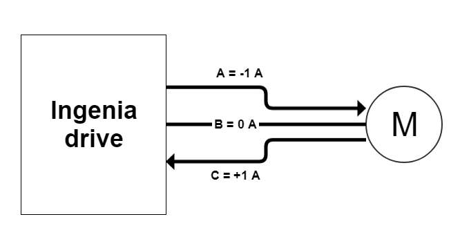
where the current relationship are:
&
. The values obtained by this register following the picture above are (for
,
and
):
-
0x2600; 0x01 - Current phase A =
-
0x2600; 0x02 - Current phase B =
-
0x2600; 0x03 - Current phase C =