0x2A0A - PWM inputs
Index | Sub Index | Name | Data Type | Acc. | Pdo Map. | NVM | Value range | Default value | Units |
|---|---|---|---|---|---|---|---|---|---|
0x2A0A | 0x01 | Max PWM frequency | UINT32 | CONST | No | No | UINT32 | 7500000 | Hz |
0x2A0A | 0x02 | PWM period 1 | UINT16 | RO | Yes | No | UINT16 | - | Reference ticks |
0x2A0A | 0x03 | PWM duty 1 | UINT16 | RO | Yes | No | UINT16 | - | Reference ticks |
0x2A0A | 0x04 | PWM period 2 | UINT16 | RO | Yes | No | UINT16 | - | Reference ticks |
| 0x2A0A | 0x05 | PWM duty 2 | UINT16 | RO | Yes | NO | UINT16 | - | Reference ticks |
This object indicates the result of the PWM input readings:
0x2A0A;0x01: maximum PWM signal frequency, for both inputs, supported by the drive (cannot be modified). This register is used for computing the reference tick time, this can be calculated as the inverse of this register:
We don't have a way to export this macro.- 0x2A0A;0x02: this register contains the measurements of HS_GPI 1 period in ticks.
- 0x2A0A;0x03: this register contains the measurements of HS_GPI 1 duty cycle in ticks.
- 0x2A0A;0x04: this register contains the measurements of HS_GPI 2 period in ticks.
- 0x2A0A;0x05: this register contains the measurements of HS_GPI 2 duty cycle in ticks.
Example:
A square signal of 10 KHz with 20% of duty cycle is injected in PWM input 1. (max PWM frequency is 7500000)
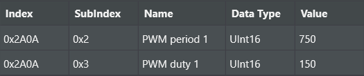
Then we can compute from measurements: Period = (750 * 0.13333 us) ≈ 100 us
Duty = 150 / 750 = 20 %
PWM readings are only available if the corresponding High speed GPI has attached the "PWM capture" function. See 0x2A10 - GPI mapping parameter register.