Inputs & Ouputs
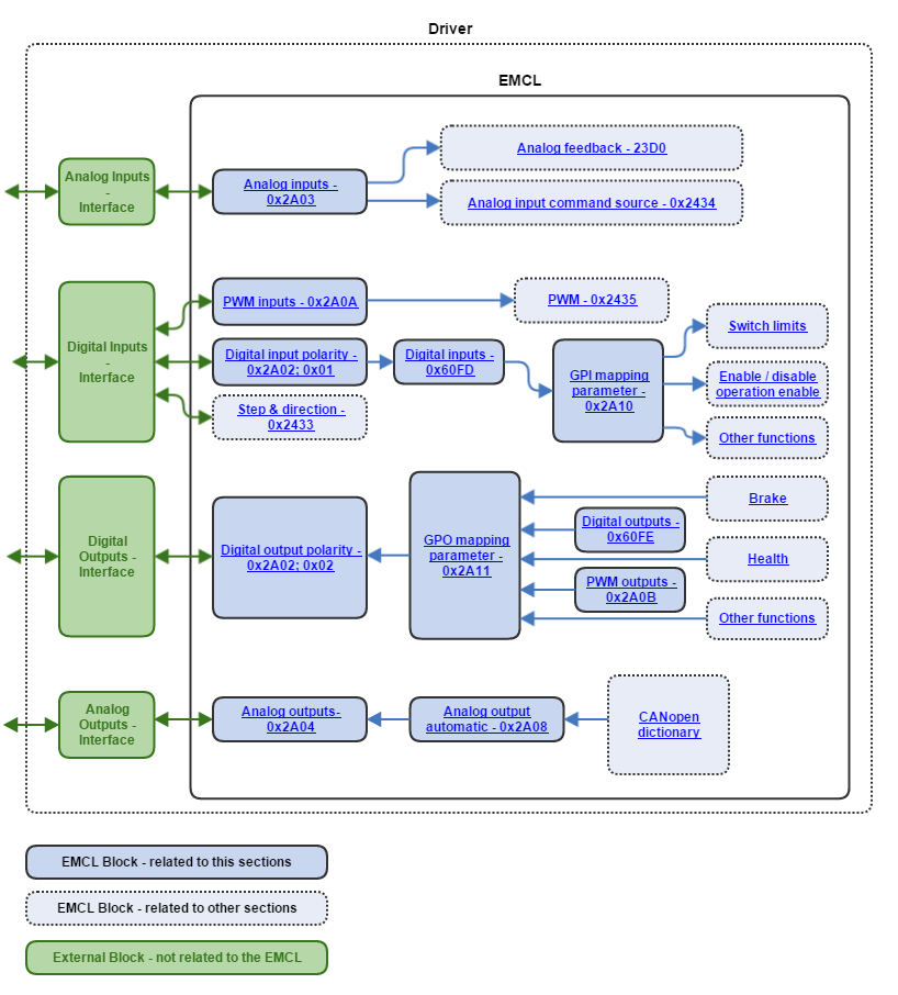
EMCL allows the user to use a set of digital and analog inputs/outputs in order to offer a more flexible solution for motion control applications. These interfaces can be used as standard I/O, for instance to read a logical signal or to light a LED, or as special functions, for instance for mapping a brake output into a digital output, or for mapping an analog command source as an analog input. The following picture depicts a block diagram of this module:
IO performance
| Update rate (kHz) | |
|---|---|
| Analogue inputs | 10 |
| Low speed digital inputs | 1 |
| High speed digital inputs | up to 30000 |
| Digital outputs | 1 |
Further information about digital and analogue IO capabilities can be found in the drive reference manual.
High speed digital inputs support all low speed digital input special functions.
High speed digital input update rates depends on the attached functionality.
Digital I/O
Digital I/O ports can be used in two ways:
- Standard I/O: This mode is oriented to provide the user with a general interface for developing its applications and interconnecting the motion controller with the neighboring subsystems at the logical line level. In this mode, the Digital inputs - 0x60FD and Digital outputs - 0x60FE registers are read and written directly by the user. Potential uses are waiting for another arbitration subsystem to give permission to the controller to execute its movements (in coordinated systems with multiple controllers), to revert the direction of motion if another subsystem gives this indication, or something as simple as to light an external LED if the driver is enclosed.
- Mapping special motion functions: This mode is provided to expand the possibilities of the motion controller with regard to interconnectability and flexibility of operation. System-critical functions like a health output or a fault reset input can be mapped to I/O ports for the neighboring systems to avoid the requirement of implementing the CANopen stack to be able to communicate with the motion controller. In this mode, the Digital inputs - 0x60FD and Digital outputs - 0x60FE registers are read and written by the system and mapped into the pertinent objects. Time-critical functionalities like brake, switch limits or target reached can be mapped to provide a faster response. The registers GPI mapping parameter - 0x2A10 and GPO mapping parameter - 0x2A11 are used to attach predefined functionalities to the digital I/O.
To offer additional flexibility, the register 0x2A02 - Digital inputs/outputs polarity is provided to set the polarity of each digital input/ouput individually.
Analog I/O
Analogous to the digital I/O, analog I/O ports can be used in two ways:
- Standard I/O: This mode is oriented to provide the user with a general interface for developing its applications and interconnecting the motion controller with the neighboring subsystems with analog I/O. In this mode, the Analog inputs - 0x2A03 and Analog outputs - 0x2A04 registers are handled directly by the user. This mode may be of use to interact with a PLC with analog I/O, or to read external sensor values.
- Special motion functions: This mode is provided to expand the possibilities of the motion controller with regard to flexibility of operation. Analog inputs may be used as command source and as a feedback, and the value of some CANopen objects can be mapped directly into an analog output too.
- Analog input as command source - 0x2434: The value of the analog input is mapped as the motion target values.
- Analog input as feedback - 0x23D0: The control loop is closed using an analog input that provides the magnitude current reading.
- Analog output automatic - 0x2A08. The value of the specified CANopen object is mapped in the analog output, scaled in the analog output range. It may be of use to monitor object values using an oscilloscope or another measurement instrument.
Health output
A digital output can be set to show the "health" state of the driver. The health state indicates if the driver is in a "operational" or in a "fault" status. This signaling might be of use in a lot of situations.
Some examples are shown below:
- The activation or deactivation of external elements if the driver enters in fault state. Some systems are composed by different elements which work together for a proper functionality. In some situations, the fault of one of these elements could produce a terrible impact for the whole system like the damage of some parts. The health output helps to notify to other elements in the system that the Ingenia drive is in the fault state.
- Driver state visualization. In systems where the Ingenia drives are inside a box or are not visible for the user, the health ouput could be used to attach a LED situated in a visible place. This LED will help to the user see if the driver is in a operation state or in a fault state without the need to disassembly the whole system.
Statusword monitoring
A digital output can be set to show the status of some bits inside the statusword register. This feature is useful if an element in the whole system need a specific information of the state machine status of the Ingenia drives.
The current implementation supports the monitorization of the next states of the statusword:
- Internal limit. Indicates if there is an element that doesn't allow to follow the motion target value.
- Target reached. Indicates if the motion target value has been reached.
Fault reset
A digital input can be set to receive a fault reset command. This feature allow to reset a fault state of the ingenia drive in situations where this command cannot be sent through the network.
For further information about the fault state, please refer to this link.
Internal generator
A GPO linked to this functionality indicates the polarity of the target command generated by the internal generator.
Further information about how to configure the internal generator is available on this link.
PWM output 1 & 2
Some GPO have the capability of working as PWM. Duty and period is configured by the register 0x2A0B.
Further information about GPO capabilities can be found in the drive reference manual.
Brake
By default, Ingenia drives have a dedicated output for attaching a external brake. However, some drives don't have this feature or the application might require and additional output to activate an other element with the same behaviour than a brake. For these cases, any GPO can be configured to work as a brake.
Additional electronics might be required if a GPO is used as brake. Further information about GPO capabilities can be found in the drive reference manual.
External shunt braking resistor
By default, Ingenia drives have a dedicated output for attaching a shunt braking resistor. However, some applications might require and additional output to work in the same way than the shunt braking resistance output. For these cases, any GPO can be configured to work as a shunt.
Further information about how shunt works on this link.
Additional electronics might be required if a GPO is used as shunt. Further information about GPO capabilities can be found in the drive reference manual.
Positive switch limit
Any input can be used as positive limit switch. This function is linked with the drive Stop manager which stops the motion (in position mode) if the switch limit is active. In the rising edge (supposing that high level means active) the position actual is copied to position demand and this last one is hold in that position until the switch limit is released.
System must be properly tuned to avoid undesired behaviours. Once the switch limit is enabled, there is not a profile applied to stop the motor, so If the drive is not able to follow correctly the position demand, it might be a quick step movement to the limit position.
Positive limit switch must be located into the end of the stroke application. It must not be used as an user input to stop the motor at any moment. When switch limit is active, the profile keeps on working, so if the switch limit is release, the motor will try to reach the position demand generated by the profiler without speed control. It may damage the system.
Negative switch limit
Any input can be used as negative limit switch. This function is linked with the drive Stop manager which stops the motion (in position mode) if the switch limit is active. In the rising edge (supposing that high level means active) the position actual is copied to position demand and this last one is hold in that position until the switch limit is released.
System must be properly tuned to avoid undesired behaviours. Once the switch limit is enabled, there is not a profile applied to stop the motor, so If the drive is not able to follow correctly the position demand, it might be a quick step movement to the limit position.
Home switch limit
Any input can be used as home switch. This function is linked to the homing mode of operation, refer to this page for further information.
Motor safety enable
Any input can be used as safety input to avoid that the drive enables the motor. If a operation enable command is received by any input (local or remote control) the drive remains into non-operational state until this input is enabled.
Combine this input with drive local control to be able to enable / disable the drive by a GPI.
PWM capture
High speed inputs are able to measure the period and duty of PWM signals and then use them as command source or feedback.
Command source
PWM measurements might be used as command source for any mode of operation of the drive. The update rate depends on the PWM frequency, so it is recommend to use a PWM signal with the same frequency than the update rate of the main loop for the mode of operation selected (position & velocity loops = 1 kHz; torque loop = 10 kHz).
Further information about how to configure an PWM input as command source can be found here.
Feedback
PWM measurements might be used as position feedback. The update rate depends on the PWM frequency, so it is recommend to use a PWM signal with the same frequency than the update rate of the main loop for the mode of operation selected (position & velocity loops = 1 kHz; torque loop = 10 kHz).
Electronic gearing command source
High speed inputs are able decode a digital encoder signal an use it as command reference.
Further information about how to configure an High speed inputs as electronic gearing command source can be found here.
Step and direction command source
High speed inputs are able decode a step and direction signals an use them as command reference.
Further information about how to configure an High speed inputs as step and direction command source can be found here.
Related objects
0x2A10 - GPI mapping parameter
0x2A11 - GPO mapping parameter
0x2A02 - Digital inputs/outputs polarity
0x2434 - Analog input command source
0x23D0 - Analog input feedback