Homing mode
Positioning systems usually need to be aware of the absolute position of the mechanics, to ensure that the desired movements are requested, and as a first protection to avoid exceeding mechanical limits. Absolute encoders, as opposed to incremental quadrature encoders, do actually provide the controller system with the absolute position of the axis. Nevertheless, due to cost reasons, most of the currently deployed systems do not use absolute encoders. Therefore, for those positioning systems that want to know the absolute position of the mechanics without incurring in a system overcost due to the presence of an absolute encoder, the process of searching for an absolute mechanical reference is a necessity. This process is usually known as homing, and the encountered position is known as home position.
Several methods to achieve an absolute reference have been devised. The most common use mechanical limits or switches, at either end of the round, or at an arbitrary zero point in the middle. The index signal counting the number of mechanical revolutions is also of use, especially in rotary systems.
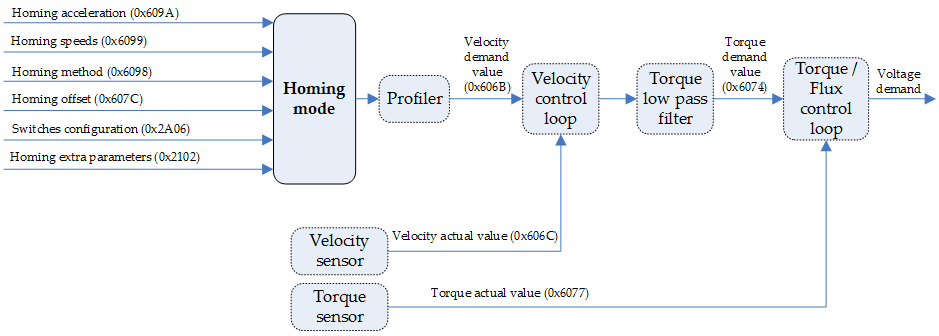
Homing methods are structured according to the following diagram:

Typically, in a homing method there are two homing speeds: the faster speed is used to find the mechanical limit, and the slower speed is used to find the index pulse. There is a compromise between search speed and homing precision, due to maximum axis deceleration and inertia. In addition to the homing speeds, the defining parameters of the homing method are the following:
- Homing signal: The homing signal refers to the magnitude measurement that indicates that the actuator has reached the home position. There are six sources of homing signals: the positive, negative and home switches, the positive and negative torque limits, and the index pulse from the encoder. They all can be used to indicate the motion controller that the actuator is in home position.
- Direction of actuation: Homing can be performed in both directions of movement/rotation.
- Whenever applicable, the position of the index pulse should also be known.
EMCL allows to map mechanical limits to any general purpose input, using the switches configuration object (deprecated from version 1.3.0) or the general purpose input mapping object for newer version. This configuration should be executed prior to entering homing mode.
Homing mode does not work with AC induction motors.
Controlword in homing mode
The homing mode uses some bits of the controlword and the statusword for mode-specific-purposes.
The binary representation of the specific controlword bits and its meaning is as follows:
Bit number: | 15 | … | 9 | 8 | 7 | 6 | 5 | 4 | 3 | … | 0 |
|---|---|---|---|---|---|---|---|---|---|---|---|
- | Halt | - | Reserved | Homing operation start | - | ||||||
The action taken is described below, depending on the value of each bit:
Name | Value | Description |
|---|---|---|
Homing operation start | 0 | Do not start homing procedure |
1 | Start or continue homing procedure | |
Halt | 0 | Execute the instruction of bit 4 |
1 | Stop axis with homing acceleration |
Statusword in homing mode
The binary representation of the register value and its meaning is as follows:
Bit number: | 15 | 14 | 13 | 12 | 11 | 10 | 9 | … | 0 |
|---|---|---|---|---|---|---|---|---|---|
- | Homing error | Homing attained | - | Target reached | - | ||||
The meaning of each bit is described below, depending on its value:
Homing error | Homing attained | Target reached | Description |
|---|---|---|---|
0 | 0 | 0 | Homing procedure is in progress |
0 | 0 | 1 | Homing procedure is interrupted or not started |
0 | 1 | 0 | Homing is attained but target is not reached |
0 | 1 | 1 | Homing mode carried out successfully |
1 | 0 | 0 | Homing error occurred; |
1 | 0 | 1 | Homing error occurred; |
1 | 1 | x | Reserved |
Related objects
0x2102 - Homing extra parameters
0x2A06 - Switches configuration (Deprecated from version 1.3.0)
