0x6098 - Homing method
Index | Sub Index | Name | Data Type | Acc. | Pdo Map. | NVM | Value range | Default value | Units |
|---|---|---|---|---|---|---|---|---|---|
0x6098 | 0x00 | Homing method | INT8 | RW | No | Yes | INT8 | 35 | - |
This object is used to select the homing method to be used among the homing methods supported.
Data description:
Object values are interpreted as follows:
Diagram interpretation
In the following figures, an encircled number indicates code selection for the homing position. Direction of movement is also indicated with an arrow. In all the diagrams, the encoder count increases as the axis is displaced to the right, in other words, the leftmost postition is the minimum position, and the rightmost position is the maximum position.
Whenever two or more movements are described, except where indicated, the first movement is always performed at the speed during search for switch or mechanical limit (see homing speeds, SubIndex 1), and subsequent movements are performed at the speed during search for zero (see homing speeds, SubIndex 2).
Homing speeds
Notice that, when index pulse is not used for homing, the speed searching for zero as described in 0x6099 - Homing speeds, SubIndex 2 is not used. The speed searching for limit or mechanical switch is used instead (see 0x6099 - Homing speeds, SubIndex 1).
Limit switches
Notice that mechanical switches connected to inputs configured as positive/negative limits, when using a homing method not involving mechanical switches, will still trigger the stop manager. See the stop manager manual page for more information.
Homing on positive following error
It is considered by the controller that a following error has occured whenever the difference between the current position and the instantaneous target position requested by the profiler is greater than the following error window for a longer time than the specified in the following error timeout object.
This method starts motor movement in a positive direction until a following error is detected. This is the home point. This homing mechanism works due to the fact that, if a mechanical limit is encountered, the instantaneous target position requested by the profiler would not be matched by the actuator due to the impossibility to continue the motion, therefore acting as an indirect indicator about the mechanical limit being encountered.
If the whole homing process is not finished within the time specified in the timeout field of the homing extra parameters register, the homing process is aborted at this point, the statusword error bit is set, and an emergency message is sent.
Homing on negative following error
It is considered by the controller that a following error has occured whenever the difference between the current position and the instantaneous target position requested by the profiler is greater than the following error window for a longer time than the specified in the following error timeout object.
This method starts motor movement in a negative direction until a following error is detected. This is the home point. This homing mechanism works due to the fact that, if a mechanical limit is encountered, the instantaneous target position requested by the profiler would not be matched by the actuator due to the impossibility to continue the motion, therefore acting as an indirect indicator about the mechanical limit being encountered.
If the whole homing process is not finished within the time specified in the timeout field of the homing extra parameters register, the homing process is aborted at this point, the statusword error bit is set, and an emergency message is sent.
Homing on positive following error and index pulse
It is considered by the controller that a following error has occured whenever the difference between the current position and the instantaneous target position requested by the profiler is greater than the following error window for a longer time than the specified in the following error timeout object.
This method starts motor movement in a positive direction until a following error is detected. This homing mechanism works due to the fact that, if a mechanical limit is encountered, the instantaneous target position requested by the profiler would not be matched by the actuator due to the impossibility to continue the motion, therefore acting as an indirect indicator about the mechanical limit being encountered.
Afterwards, the axis is moved in a negative direction until the first index pulse is received. When the first index pulse is received, the position where this pulse is received is considered to be the home point.
If the whole homing process is not finished within the time specified in the timeout field of the homing extra parameters register, the homing process is aborted at this point, the statusword error bit is set, and an emergency message is sent.
Homing on negative following error and index pulse
It is considered by the controller that a following error has occured whenever the difference between the current position and the instantaneous target position requested by the profiler is greater than the following error window for a longer time than the specified in the following error timeout object.
This method starts motor movement in a negative direction until a following error is detected. This homing mechanism works due to the fact that, if a mechanical limit is encountered, the instantaneous target position requested by the profiler would not be matched by the actuator due to the impossibility to continue the motion, therefore acting as an indirect indicator about the mechanical limit being encountered.
Afterwards, the axis is moved in a positive direction until the first index pulse is received. When the first index pulse is received, the position where this pulse is received is considered to be the home point.
If the whole homing process is not finished within the time specified in the timeout field of the homing extra parameters register, the homing process is aborted at this point, the statusword error bit is set, and an emergency message is sent.
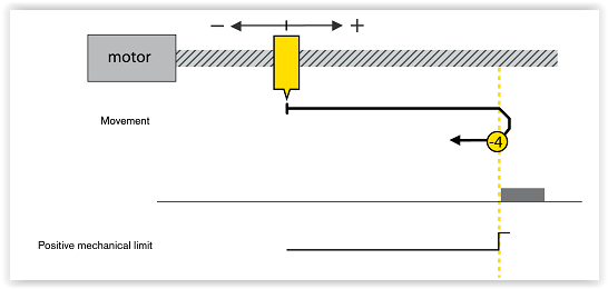
Homing on the positive mechanical limit
This method starts motor movement in a positive direction until a mechanical limit is detected. This is the home point. It is considered that a mechanical limit has been reached whenever the current torque exceeds the torque limit of the homing extra parameters register. If the mechanical limit is not reached within the time specified in the timeout field of the homing extra parameters register, the homing process is aborted at this point, the statusword error bit is set, and an emergency message is sent.
Homing on the negative mechanical limit
This method starts motor movement in a negative direction until a mechanical limit is detected. This is the home point. It is considered that a mechanical limit has been reached whenever the current torque exceeds the torque limit of the homing extra parameters register. If the mechanical limit is not reached within the time specified in the timeout field of the homing extra parameters register, the homing process is aborted at this point, the statusword error bit is set, and an emergency message is sent.
Homing on the positive mechanical limit and index pulse
This method starts motor movement in a positive direction until a mechanical limit is detected. It is considered that a mechanical limit has been reached whenever the current torque exceeds the torque limit of the homing extra parameters register.
Afterwards, the axis is moved in a negative direction until the first index pulse is received. When the first index pulse is received, the position where this pulse is received is considered to be the home point.
If the whole homing process is not finished within the time specified in the timeout field of the homing extra parameters register, the homing process is aborted at this point, the statusword error bit is set, and an emergency message is sent.
Homing on the negative mechanical limit and index pulse
This method starts motor movement in a negative direction until a mechanical limit is detected. It is considered that a mechanical limit has been reached whenever the current torque exceeds the torque limit of the homing extra parameters register.
Afterwards, the axis is moved in a positive direction until the first index pulse is received. When the first index pulse is received, the position where this pulse is received is considered to be the home point.
If the whole homing process is not finished within the time specified in the timeout field of the homing extra parameters register, the homing process is aborted at this point, the statusword error bit is set, and an emergency message is sent.

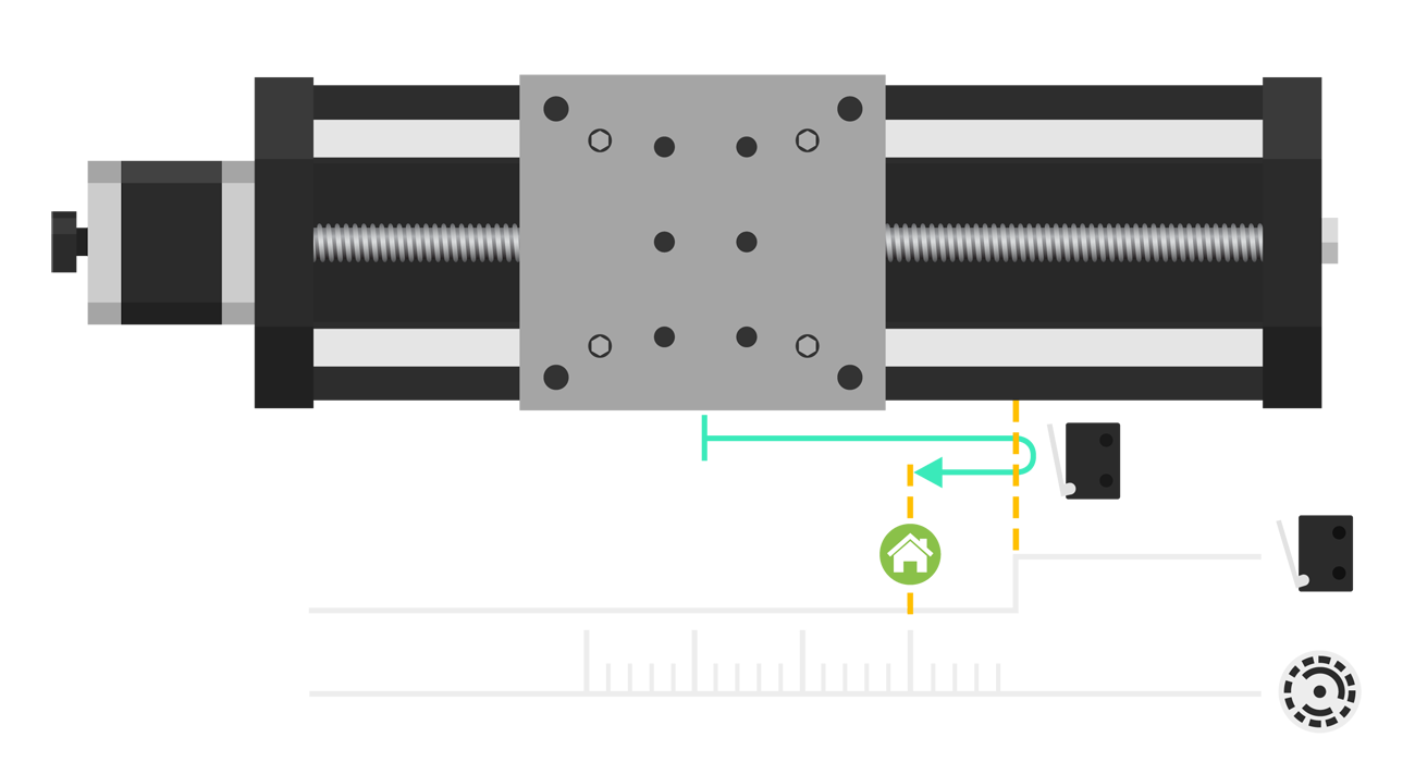
Homing on the negative limit switch and index pulse
This method starts motor movement in a negative direction until a change on the output signal of an electromecanical switch placed at the leftmost position is detected.
Afterwards, the axis is moved in a positive direction until the switch signal toggles its value again. When the switch signal has toggled, the movement continues until an index pulse is received. This is the home point.
If the whole homing process is not finished within the time specified in the timeout field of the homing extra parameters register, the homing process is aborted at this point, the statusword error bit is set, and an emergency message is sent.
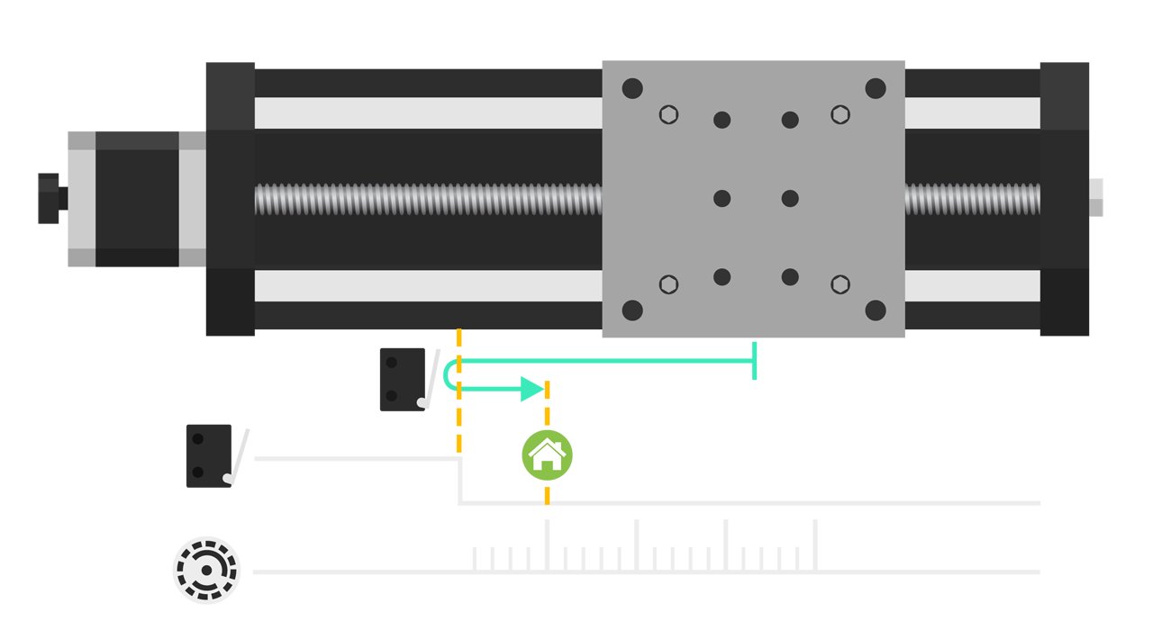
Homing on the positive limit switch and index pulse
This method starts motor movement in a positive direction until a change on the output signal of an electromecanical switch placed at the rightmost position is detected.
Afterwards, the axis is moved in a negative direction until the switch signal toggles its value again. When the switch signal has toggled, the movement continues until an index pulse is received. This is the home point.
If the whole homing process is not finished within the time specified in the timeout field of the homing extra parameters register, the homing process is aborted at this point, the statusword error bit is set, and an emergency message is sent.
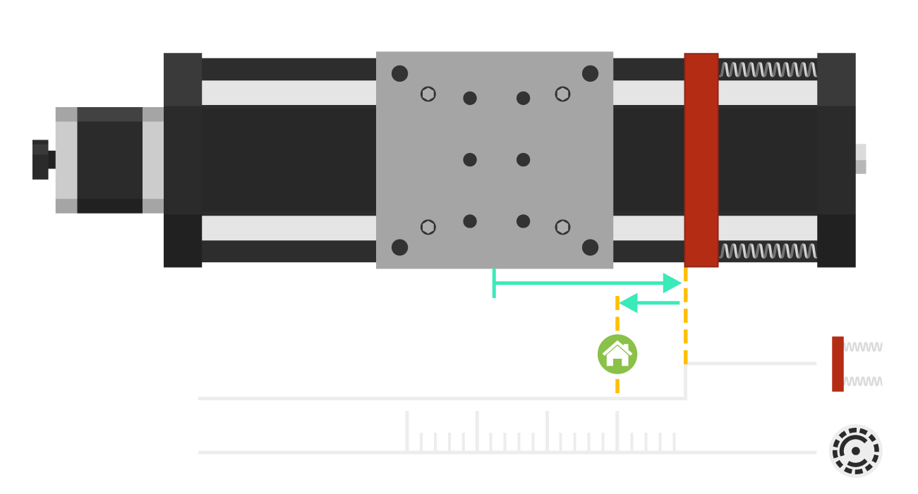
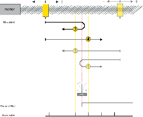
Homing on the positive home switch and index pulse
Positive and negative home switch methods only differ in the logical interpretation of the output of the electromechanical home switch. In positive home switch methods, the actuator is considered to be to the left of the home switch when its output is a logical 0, and to the right of the home switch when its output is a logical 1. On the other hand, negative home switch methods consider that the actuator is to the left of the home switch method when its output is a logical 1, and to the right of the home switch when its output is a logical 0. Aside from this, the behavior of both methods is exactly the same.
The homing process on the positive home switch and index pulse method starts motor movement towards home position (remember that it is known if the actuator is to the left or to the right of the home switch) until a change on the output signal of an electromecanical switch placed at the home position is detected.
Afterwards, the behavior between methods 3 and 4 differ. In method 3 the actuator is moved in a negative direction until the first index pulse is received. On the other hand, in method 4 the actuator is moved in a positive direction until the first index pulse is received. When the first index pulse is received, the position where this pulse is received is considered to be the home point.
If the whole homing process is not finished within the time specified in the timeout field of the homing extra parameters register, the homing process is aborted at this point, the statusword error bit is set, and an emergency message is sent.
Notice that, when searching for a switch in the home position, as opposed to when searching for a switch limit, the search for the switch ends at the very moment that the switch ouptut signal is toggled. Instead, when searching for switch limits, the search for the switch ends when the output signal is toggled again after performing a movement in the opposite direction that the switch search direction.
Nevertheless, notice that the home switch may be toggled again when searching for the first index pulse whenever this index pulse is searched in the opposite direction that the home switch was searched.
Homing on the negative home switch and index pulse
See homing on the positive home switch and index pulse. The only difference between homing on the positive switch and index pulse and on the negative switch and index pulse is the logical interpretation of the output signal of the electromechanical home switch.
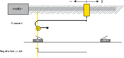
Homing on the negative limit switch
This method starts motor movement in a negative direction until a change on the output signal of an electromecanical switch placed ad the leftmost position is detected.
Afterwards, the axis is moved in a positive direction until the switch signal toggles its value again. This is the home point.
If the whole homing process is not finished within the time specified in the timeout field of the homing extra parameters register, the homing process is aborted at this point, the statusword error bit is set, and an emergency message is sent.
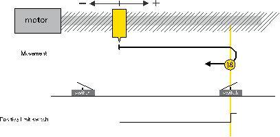
Homing on the positive limit switch
This method starts motor movement in a positive direction until a change on the output signal of an electromecanical switch placed ad the rightmost position is detected. This is the home point.
Afterwards, the axis is moved in a negative direction until the switch signal toggles its value again. This is the home point.
If the whole homing process is not finished within the time specified in the timeout field of the homing extra parameters register, the homing process is aborted at this point, the statusword error bit is set, and an emergency message is sent.
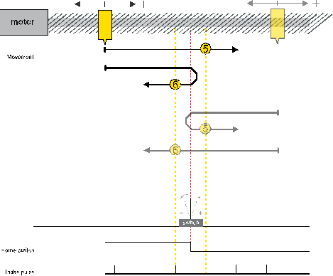
Homing on the positive home switch
Positive and negative home switch methods only differ in the logical interpretation of the output of the electromechanical home switch. In positive home switch methods, the actuator is considered to be to the left of the home switch when its output is a logical 0, and to the right of the home switch when its output is a logical 1. On the other hand, negative home switch methods consider that the actuator is to the left of the home switch method when its output is a logical 1, and to the right of the home switch when its output is a logical 0. Aside from this, the behavior of both methods is exactly the same.
The homing process on the positive home switch method starts motor movement towards home position (remember that it is known if the actuator is to the left or to the right of the home switch) until a change on the output signal of an electromecanical switch placed at the home position is detected.
At this point, the behavior between methods 19 and 20 differs. In method 19 it is considered that the home point is encountered whenever a transition of the output signal from logical 1 to logical 0 is detected, while in method 20 it is considered that the home point is encountered whenever a transition of the output signal from logical 0 to logical 1 is detected.
If the whole homing process is not finished within the time specified in the timeout field of the homing extra parameters register, the homing process is aborted at this point, the statusword error bit is set, and an emergency message is sent.
Homing on the negative home switch
See also homing on the positive home switch. The only difference between homing on the positive switch and index pulse and on the negative switch and index pulse is the logical interpretation of the output signal of the electromechanical home switch. In method 21 it is considered that the home point is encountered whenever a transition of the output signal from logical 1 to logical 0 is detected, while in method 22 it is considered that the home point is encountered whenever a transition of the output signal from logical 0 to logical 1 is detected.
Homing on negative index pulse
This method starts motor movement in a negative direction until an index pulse is received. This is the home point. If an index pulse has not been received within the time specified in the timeout field of the homing extra parameters register, the homing process is aborted at this point, the statusword error bit is set, and an emergency message is sent.
This movement is performed at the speed during search for zero (see homing speeds, SubIndex 2).
Homing on positive index pulse
This method starts motor movement in a positive direction until an index pulse is received. This is the home point. If an index pulse has not been received within the time specified in the timeout field of the homing extra parameters register, the homing process is aborted at this point, the statusword error bit is set, and an emergency message is sent.
This movement is performed at the speed during search for zero (see homing speeds, SubIndex 2).
Homing on current position
Home position is the current position. This is the only homing method that does not require the controller to be in operation enabled state, and no timeout is implemented.