PWM Command Source
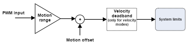
A PWM signal can be used as a command source for a motion application. For this signal to be useful to the control system, the magnitude value is decoded from the PWM signal. Thereafter, some linear transformations (scaling and offset) may be applied if desired, and afterwards system limits are applied. The potentially modified magnitude value is what is stored in the pertinent object.
In addition to those features, and only for velocity modes, a deadband is provided to prevent overcontrol near to the target velocity due to an excess of sensitivity.
The EMCL offers this option for the next modes of operation:
- Open loop vector
- Open loop scalar
- Profile position
- Velocity mode
- Profile velocity
- Profile torque
- Cyclic synchronous position
- Cyclic synchronous velocity
- Cyclic synchronous torque
The register 0x2435 - PWM command source is used to configure the PWM input parameters.
PWM input parameters are:
PWM input motion range. Contains the whole range in motion units. This range value may exceed the maximum system limits, but the final demand value will be limited by the system limits module. For reverse motion, the range value must be negative.
PWM input motion offset. Applies an offset value in motion units once the PWM input has been scaled. This register can be used to correct PWM offsets, get asymmetric motion ranges and determine the 0 value.
The motion offset is only used in single input mode. For dual input mode a 0% of duty always means a 0 motion value and a 100% means a ±motion range / 2. In both modes, the final total motion range is equal to the value into the PWM input motion range.
PWM input velocity deadband. Generates a 0 output if the input value (scaled and, therefore, in motion units) does not overcome the deadband value. This characteristic allows reducing sensitivity at low speeds.
This feature is only used in velocity modes
In addition to the aforementioned, two mode of operation exist:
- Single input: The demanded value is computed using the PWM signal exclusively.
- Dual input: The demanded value is computed using the PWM signal for the absolute value of the desired motion, and another digital input for the direction of motion.
Whereas the single input mode uses the range from 0 to 100% of the duty, the dual input uses a effective duty of the 200%. Therefore, the dual input is more suitable for applications where additional precision is required, while the single input can be used whenever an additional digital input is not available, or simply in cases where that much precision is not required and simplicity is preferred.
It is recommended to use a PWM frequency between 2 kHz and 20 kHz. Higher frequencies could be read but will lead to a lower resolution with no improvement in performance. Frequencies below 2 kHz can lead to control problems.
Important: for using PWM command source, corresponding HSGPI pin/s must be initialized with PWM capture input function according: GPI mapping parameter.
Usage examples
Case 1
| Desired configuration | Result | |
|---|---|---|
| Mode of operation | Cyclic synchronous position | 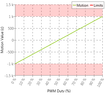 |
| PWM cmd mode | Single input | |
| Motion range | 2000 counts | |
| Motion offset | -1000 counts | |
| Position limits | ± 1000 | |
Case 2
| Desired configuration | Result | |
|---|---|---|
| Mode of operation | Profile velocity | 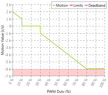 |
| PWM cmd mode | Single Input | |
| Motion range | -10000 counts / 2 | |
| Motion offset | 2000 counts | |
| Velocity deadband | 1000 | |
| Velocity limit | ± 6000 | |
Finally, the registers PWM duty actual and PWM period actual give information about the current PWM signal.