Cyclic synchronous position mode
In cyclic synchronous position mode, EMCL closes the control loop with a magnitude proportional to the current position. This mode is very similar to the profile position control mode, with one fundamental difference: the trajectory profiler is omitted. The following diagram depicts how this mode works internally:
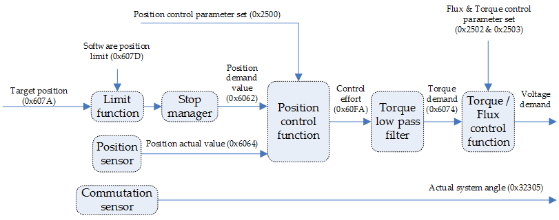
The value of the target position register, as obtained from the command source, is processed immediately on reception (system limits, etc.). After estimating the control effort and converting it to torque, the torque demand is delivered to the control unit. Upon reaching target position, a statusword is issued as a notification to other nodes.
The fact that the internal trajectory profiler is not used conditions the control parameters and the master-controller relationship in several ways:
- For the master to close a control loop, it needs to have available the sensor readings. Nevertheless, the sensors are placed in the motion controller, and therefore network intercommunication is required not only to receive the updated on the target torque, but also for the master to receive sensor data from the motion controller.
- The presence of network protocol and network lag instead of direct memory access from the motion controller makes this mode inherently less responsive than modes that use the internal profiler.
- If the master chooses to close a less responsive loop, the parameters of the controller can not be chosen as agressively as if the control system was more responsive.
- If the master attempts to close a highly responsive loop, a high percentage of the communication bandwidth should be devoted to communications related to the control loop, which may be undesirable.
As an attempt to improve motion smoothness for masters with insufficient target update rates, linear interpolation is applied to the incoming data. The interpolation time base can be chosen through the interpolation time period register.
Cyclic synchronous position mode is not supported for AC induction motors.
Controlword in cyclic synchronous position mode
The cyclic synchronous position mode uses no mode specific bit of the controlword. The Target position will be automatically processed after reception.
Statusword in cyclic synchronous position mode
The binary representation of the register value and its corresponding meaning is as follows:
Bit number: | 15 | 14 | 13 | 12 | 11 | 10 | 9 | … | 0 |
|---|---|---|---|---|---|---|---|---|---|
| - | Following error | Drive follows the command value | - | - | - | |||
The meaning of each bit is described below, depending on its value:
Name | Value | Description |
|---|---|---|
Drive follows the command value
| 0 | The drive is not able to follow the target value |
1 | The drive follows the target value | |
| Following error | 0 | No following error |
| 1 | Following error |
Example
If the target value is out of the software position limits range, the actuator will be stopped at the limit and the bit 12 value of the statusword will be 0 (The drive is not able to follow the target value)
Related objects
0x6062 - Position demand value
0x6064 - Position actual value