0x2500 - Position control parameters set
Index | Sub Index | Name | Data Type | Acc. | Pdo Map. | NVM | Value range | Default value | Units |
|---|---|---|---|---|---|---|---|---|---|
0x2500 | 0x01 | Proportional constant | UINT32 | RW | No | Yes | UINT32 | 1000 | ‰ rated torque / increments |
0x2500 | 0x02 | Integral constant | UINT32 | RW | No | Yes | UINT32 | 5 | ‰ rated torque / (increments * s) |
0x2500 | 0x03 | Derivative constant | UINT32 | RW | No | Yes | UINT32 | 40000 | (‰ rated torque * s) / increments |
0x2500 | 0x04 | Integral antiwindup constant | UINT32 | RW | No | Yes | UINT32 | 0 | increments / ‰ rated torque |
0x2500 | 0x05 | Velocity feedforward constant | UINT32 | RW | No | Yes | UINT32 | 0 | (‰ rated torque * s) / increments |
0x2500 | 0x06 | Acceleration feedforward constant | UINT32 | RW | No | Yes | UINT32 | 0 | (‰ rated torque * s2) / increments |
0x2500 | 0x07 | Integral limit | UINT32 | RW | No | Yes | 0-1000 | 1 | ‰ rated torque |
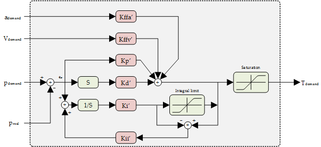
The filter implemented in the position control loop is a parallel PID with acceleration and velocity feed-forward.
The output contribution of the integral term could be controlled by using the Integral Limit factor and the Antiwindup contant. This mechanism is useful to reduce the overshoot or response time of the system. In situations where the position demanded is not physically reachable or the torque is saturated, the contribution of the integral term will increase continuously as the position error will never be zero. When the error direction is reversed, due to a position demand change or after an overshoot correction, the control loop will require some time to react as the accumulated integral term will be high. Integral Limit helps to reduce the contribution of the accumulated integral error and antiwindup constant could control the behavior of the integral part once saturation is reached.
Setting an Antiwindup constant equal to Integral constant will stop the integral contribution once the integral limit is reached.
Next Figure shows a diagram of the loop.
The equivalent equation of control loop is the following one:
The integral of the error will be accumulated only within a certain limits configurable by means of the integral limit constant. Once the accumulated error reaches this limit, the system will stop increasing the integral.
The equation could be expressed in digital space as following:
The simplified equivalent equation of the implemented PID (without feedforwards) is:
Where:
Due to optimization of computational time we consider the Tsampling included into the constants value. We also include an additional scaling value to give more resolution. Therefore, the constants used sent to the controller will be related with the internal ones in the following way:
Where
Giving a final scaling of
The integral limit is also scaled as stated in the following equation:
So, if we want a constant Kp' with a 0.4 value we must set a 26214 into object 0x2500 SubIndex 1 that corresponds to the Kp constant in position loop.
This object defines the constants of the position control loop.
Proportional part
The proportional part consists in the product between the error signal and the proportional constant (Kpp). This component plays an important role when the error signal is large, but its action is reduced as the signal decreases. The consequence of this effect is the appearance of a permanent error, which means the proportional part never actually solves the system error completely.
The proportional constant will determine the permanent error, being less when the proportional constant is bigger. Sufficiently high proportional constant values can be established to render the permanent error almost null, but in most cases these values will only be optimum in a particular portion of the total control range, with the optimum values being different for each portion of the range. A limit does also exist however in the proportional constant, after which the system will in some cases reach values greater than those desired. This phenomenon is called overshoot, and must not exceed 30% for safety reasons, although it is desirable for the proportional part not to produce any overshoot at all.
The proportional part does not consider time, so the best way to solve the permanent error and to make the system contain some component that considers the variation with respect to time is by including and configuring integral and derivative actions.
Integral part
The purpose of the integral part is to reduce and remove the stationary status error, caused by the proportional mode.
The error is integrated, with the function of averaging it or adding it for a particular period of time; it is then multiplied by the Kpi integration constant. The integral reply is then added to the proportional mode, with the aim of obtaining a stable response from the system without any stationary error.
Derivative part
The derivative action is shown when there is a change in the absolute error value (if the error is constant, only the proportional and integral modes act).
The function of the derivative action is to keep the error to a minimum by correcting it in proportion to the same velocity at which it occurs; this thereby prevents the error from increasing.
A greater derivative action corresponds to faster change capacity by the controller. Derivative action is suitable when there is a load change, for example, and we cannot wait for the integral action to correct the error by itself.