Velocity mode
When EMCL works in velocity mode, it uses an open loop v/f control, where the applied voltage is proportional to the applied frequency, with the aim to better control the speed of the motor. Therefore, maximum voltage is applied whenever the demanded velocity is the maximum. In addition, in order to obtain a soft start of the motor, the applied frequency (and therefore the applied voltage) are limited by a fully configurable ramp function. Notice that this mode of operation works analogously to a frequency inverter control device.
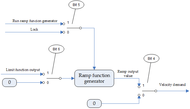
The structure of the velocity mode processing is depicted in the following schematic:

Velocity mode only works for brushless motors and AC induction motors.
Controlword in velocity mode
The binary representation of the register value and its corresponding meaning is as follows:
| Register | Bit number: | 15 | … | 9 | 8 | 7 | 6 | 5 | 4 | 3 | … | 0 |
|---|---|---|---|---|---|---|---|---|---|---|---|---|
0x6040 |
| - | Halt | - | Reference ramp | Unlock ramp | Enable ramp | - | ||||
The action taken is described below, depending on the value of each bit:
Name | Value | Description |
|---|---|---|
Enable ramp
| 0 | Velocity demand is forced to be zero |
1 | Velocity demand value follows ramp output value | |
Unlock ramp
| 0 | Ramp output value is locked to current output value |
1 | Ramp output value ramps to input value | |
Reference ramp
| 0 | Ramp input value is set to zero |
1 | Ramp input value is set to velocity limit function output | |
Halt
| 0 | No command |
1 | Motor is stopped |
The following figure represents the effect of each controlword bit.

Statusword in velocity mode
The cyclic synchronous position only uses the internal limit active (bit 11) of the statusword to signal that vl target velocity is out of vl velocity min max amount range.
Related objects
0x6046 - vl velocity min max amount
0x6048 - vl velocity deceleration
