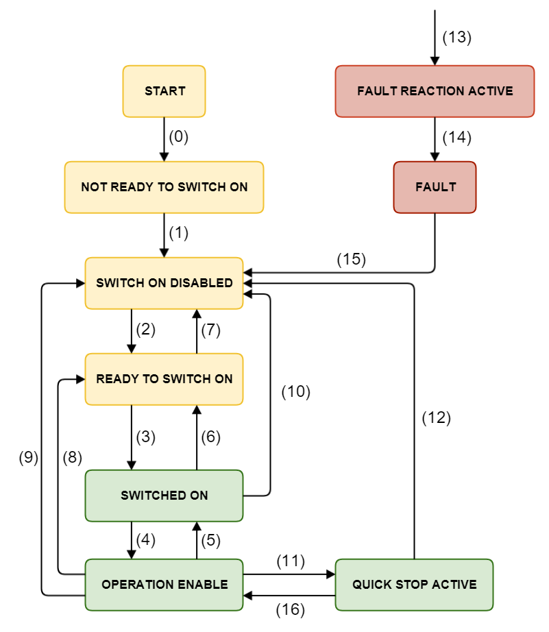
CiA 402 State Machine
The EMCL controller state machine is shown below, along with a description of each one of the defined states:
The following table indicates which functionalities can be activated on every state. External brake can only applied if it is present, and high-level power applied is only selectable in controllers with an embedded contactor/switch for the power stage.
Function | Not ready to switch on | Switch on disable | Ready to switch on | Switched on | Operation enabled | Quick stop active | Fault reaction active | Fault |
|---|---|---|---|---|---|---|---|---|
Brake applied, if present | Yes | Yes | Yes | Yes | Yes / No ( * ) | Yes / No ( * ) | Yes / No ( * ) | Yes |
Low-level power applied | Yes | Yes | Yes | Yes | Yes | Yes | Yes | Yes |
High-level power applied | Yes / No ( ** ) | Yes / No ( ** ) | Yes / No ( ** ) | Yes | Yes | Yes | Yes | Yes / No ( ** ) |
Drive function enabled | No | No | No | No | Yes | Yes | Yes | No |
Configuration allowed | Yes | Yes | Yes | Yes | No | No | No | Yes |
Shunt control enabled | No | No | No | No | Yes | Yes | Yes | No |
( * ) In some states, brake could be activated and/or deactivated manually.
( ** ) In some controllers, high-level switch is not present and therefore high level power could not be deactivated.
The controller supports the following events and actions.
Transition | Event | Action |
|---|---|---|
0 | Automatic transition after power-on or reset application. | Drive device self-test and/or self initialization is performed. |
1 | Automatic transition after initialization. | Communications are activated. |
2 | Shutdown command received from control device or local signal. | None. |
3 | Switch on command received from control device and enable signal is activated (if available) or local signal. | The high-level power is switched on. |
4 | Enable operation command received from control device and enable signal is activated (if available) or local signal. | The drive function is enabled, Initial angle determination process is executed and all internal set-points cleared. |
5 | Disable operation command received from control device or enable signal is deactivated (if available) or local signal. | The drive function is disabled. |
6 | Shutdown command received from control device or enable signal is deactivated (if available) or local signal. | The high-level power is switched off. |
7 | Quick stop or disable voltage command received from control device or local signal. | None. |
8 | Shutdown command received from control device or enable signal is deactivated (if available). | The drive function is disabled, and the high-level power is switched off. |
9 | Disable voltage command from control device or local signal. | The drive function is disabled, and the high-level power is switched off. |
10 | Disable voltage or quick stop command received from control device or local signal. | The high-level power is switched off. |
11 | Quick stop command received from control device or local signal. | The quick stop function is started. |
12 | Automatic transition when the quick stop function is completed or disable voltage command is received from control device (depending on 0x605A - Quick stop option code). | The drive function is disabled, and the high-level power is switched off. |
13 | Fault signal. | The configured fault reaction function is executed. |
14 | Automatic transition. | The drive function is disabled, and the high-level power is switched off. |
15 | Fault reset command received from control device or local signal. | A reset of the fault condition is carried out, if no fault exists currently on the drive device; after leaving the Fault state, the Fault reset bit in the controlword is cleared by the control device. |
| 16 | Enable operation command from control device. | The drive function is enabled. |
When drive function is disabled, no energy will be supplied to the motor. Target or set-point (torque, velocity, position) in that situation are not processed.
High-level power is switched off only in systems with contactors or switches for this purpose.
Enable signal will affect only if it is marked as available in the corresponding register. See Enable / disable input for further information.

