NMT
The network management (NMT) protocols provide services for network initialization, error control and device status control. NMT objects are used for executing NMT services. The NMT follows a master-slave structure and therefore requires that one CANopen device in the network fulfils the function of the NMT master. All other CANopen devices are regarded as NMT slaves. An NMT slave is uniquely identified in the network by its Node-ID, a value in the range of 1 to 127.
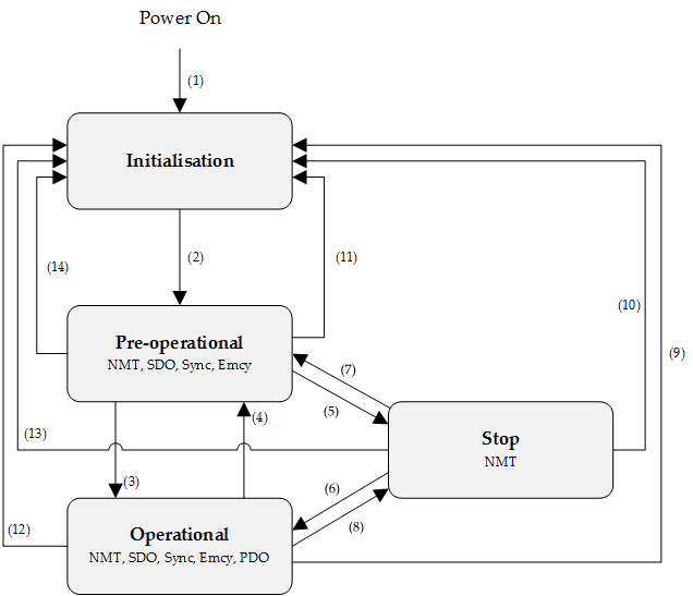
The NMT state machine defines the communication status for CANopen devices.
Transition | Event |
|---|---|
(1) | After power on the system goes directly to initialization state |
(2) | Once initialization is completed the system enters to Pre-operational state |
(3), (6) | Reception of Start remote node command |
(4), (7) | Reception of Enter pre-operational state command |
(5), (8) | Reception of Stop remote node command |
(9), (10), (11) | Reception of Reset node command |
(12), (13), (14) | Reception of Reset communication command |
NMT state initialization
The initialization state could be divided into three sub-states that are executed in a sequential way: Initializing (performs the basic CANopen initializations), Reset application (in where all manufacturer-specific and standardized profile area parameters are set) and Reset communication (where the communication profile and parameters are set).
At the end of initialization state the device sends a boot-up message and goes directly to Pre-Operational state.
NMT state pre-operational
In Pre-Operational state, the communication using SDO messages is possible. PDO message are not yet defined and therefore communication using these message is not allowed. The device will pass to Operational message after receiving a NMT start node command.
Normally the master puts a node in Pre-Operational state during the set-up and configuration of device parameters.
NMT state operational
In Operational state all kind of messages are active, even PDO messages.
NMT state stopped
When entering in Stopped state, the device is forced to stop all communications with the exception of the NMT commands. (Node Guarding & Life Guarding).
NMT states and communication object relation
Following table shows the relation between communication states and communication objects. Services on the listed communication objects may only be executed if the devices involved in the communication are in the appropriate communication states
| Pre-Operational | Operational | Stopped |
|---|---|---|---|
NMT services | X | X | X |
NMT error control | X | X | X |
PDO |
| X |
|
SDO | X | X |
|
Sync object | X | X |
|
Emergency object | X | X |
NMT services
The structure of each NMT service command is as follows:
COB-ID (hex) | Number of Bytes | Data field | |
|---|---|---|---|
Byte 1 | Byte 2 | ||
000 | 2 | Command specifier | Node ID |
The possible NMT services commands are the followings:
Command specifier (hex) | Command description |
|---|---|
01 | Start remote node |
02 | Stop remote node |
80 | Enter pre-operational |
81 | Reset node |
82 | Reset communication |
Example of NTM services:
COB-ID (hex) | Number of Bytes | Data (hex) | Description |
|---|---|---|---|
000 | 2 | 80 01 | NMT Host commands node 1 into Pre-Operational state |
000 | 2 | 01 01 | NMT Host commands node 1 into Operational state |
000 | 2 | 02 01 | NMT Host commands node 1 into Stopped state |
000 | 2 | 82 01 | NMT Host commands a communication reset to node 1 |
701 | 1 | 00 | Node 1 response with a boot-up message |
NMT error control
Protocol node guarding
The NMT Master can monitor the communication status of each node using the Node Guarding protocol.
During node guarding, a controller is polled periodically and is expected to respond with its communication state within a pre-defined time frame. Note that responses indicating an acceptable state will alternate between two different values due to a toggle bit in the returned value. If there is no response, or an unacceptable state occurs, the NMT master could report an error to its host application.
The NMT master sends a node guarding request using the following a Remote Frame message:
COB-ID (hex) | Number of Bytes | RTR |
|---|---|---|
700 + Node ID | 0 | 1 |
The NMT slave will generate a node guarding answer using the following message:
COB-ID (hex) | Number of Bytes | RTR | Data field (Byte 1) | |
|---|---|---|---|---|
Bit 7 | Bit 6 to 0 | |||
700 + Node ID | 1 | 0 | Toggle | NMT communication state |
Note that the slave answers toggling a bit between consecutive responses. The value of the toggle bit of the first response after the guarding protocol becomes actives is zero.
The state of the heartbeat producer could be one of the followings:
Communication State value (hex) | State definition |
|---|---|
00 | Boot-up |
04 | Stopped |
05 | Operational |
7F | Pre-operational |
Example of NMT Node guarding:
COB-ID (hex) | Number of Bytes | RTR | Data field (hex) | Description |
|---|---|---|---|---|
701 | 0 | 1 | - | Master sends a CAN remote frame without data to node 1. |
701 | 1 | 0 | 7F | Node 1 sends the actual NMT state (pre-operational) toggling the 7th bit. |
701 | 0 | 1 | - | Master sends a CAN remote frame without data to node 1. |
701 | 1 | 0 | FF | Node 1 sends the actual NMT state (pre-operational) toggling the 7th bit. |
Protocol heartbeat
The heartbeat protocol defines an error control service without need for remote frame. A heartbeat producer (in this scope a controller) transmits a Heartbeat message cyclically. Transmit cycle of heartbeat message could be configured using the object Producer heartbeat time (0x1017). If the Heartbeat is not received by the consumer (in this scope a master) within an expected period of time (normally specified as Consumer heartbeat time) it could report an error to its host application.
Devices based on emcl are only heartbeat producers.
The heartbeat message generated by the producer will be as follows:
COB-ID (hex) | Number of Bytes | Data field (Byte 1) | |
|---|---|---|---|
Bit 7 | Bit 6 to 0 | ||
700 + Node ID | 1 | Reserved | NMT communication state |
The state of the heartbeat producer could be one of the followings:
Communication State value (hexadecimal) | State definition |
|---|---|
00 | Boot-up |
04 | Stopped |
05 | Operational |
7F | Pre-operational |
Example of NMT heartbeat:
COB-ID (hex) | Number of Bytes | Data field (hex) | Description |
|---|---|---|---|
705 | 1 | 7F | Node 5 sends a heartbeat indicating pre-operational state. |
705 | 1 | 7F | After producer heartbeat time, Node 5 sends again a heartbeat indicating pre-operational state. |
Protocol lifeguarding
In Life guarding protocol the NMT slave monitors the status of the NMT master. This protocol utilizes the objects Guard time (0x100C) and Life time factor (0x100D) to determine a "Lifetime" for each NMT slave (Lifetime = Guard Time * Life Time Factor). If a node does not receive a Node Guard message within its Lifetime, the node assumes communication with the host is lost sends an emergency message and performs a fault reaction. Each node may have a different Lifetime.
Example of NMT life guarding:
COB-ID (hex) | Number of Bytes | RTR | Data field (hex) | Description |
|---|---|---|---|---|
701 | 0 | 1 | - | Master sends a CAN remote frame without data to node 1 |
701 | 0 | 1 | - | Master sends a CAN remote frame without data to node 1 |
… | … | … | … | Delay Higher than Guard Time * Life Time Factor |
81 | 8 | 0 | 30 81 11 00 00 00 00 00 | Node 1 send an EMCY indicating the lifeguard error |
Note: to start the Life Guarding protocol, both Guard Time and Life Time Factor need to be different than 0, and a first CAN remote frame without data needs to be send to each node.
Protocol boot-up
An NMT slave issues the Boot-up message to indicate to the NMT-Master that it has entered the state Pre-operational from state Inititalising.
Example of NMT Boot-up:
COB-ID (hex) | Number of Bytes | Data field (hex) | Description |
|---|---|---|---|
701 | 1 | 00 | Node 1 sends a boot-up NMT message |