Communications
The Jupiter Servo Drive provides the following network communication interfaces for configuration and operation:
RS232 interface
Jupiter Servo Drive is provided with RS485 interface, but can be supplied with RS232 isolated interface. Please, contact with Ingenia to purchase Jupiter Servo Drive with RS232.
All the interfaces can be used to connect the Jupiter with Ingenia MotionLab2 suite or a custom application built with the supplied controller libraries. With the objective of configure and diagnostic CAN communication, CANopen and another communication interface can be used simultaneously.
USB interface
Jupiter Servo Drive supports Universal Serial Bus (USB), a standard interface for connecting peripheral devices to a host computer. The following table shows main USB interface specifications:
Specification | Details |
|---|---|
USB version | USB 2.0 (full speed) |
Data rate | Up to 12 Mbps |
Maximum cable length | 5 meters (16 feet) |
USB application
USB interface is only recommended for configuration purposes. For noisy environments, CANopen interface is strongly recommended.
USB powered drive
The Jupiter can be powered from USB for configuration purposes without the need of an external power supply. With USB supply the Jupiter only basic configuration and programming options are available. The is not capable of driving a motor or sensing a feedback input due to USB power limitations. An internal switch automatically chooses the power source prioritizing the Supply and shunt connector. Please note that several functionalities will not be available when powered from USB.
USB wiring recommendations
Although USB is a widespread communication standard it has some disadvantages when operating in noisy environments. Following are some wiring recommendations.
- Use shielded cable with the shield connected to PC end. Shield of micro USB connector is not connected on Jupiter.
- Do not rely on an earthed PC to provide the Jupiter Servo Drive earth connection. The drive must be earthed through a separate circuit.
- Avoid creating ground loops by using isolated power supplies.
- Shortest cables are preferred.
USB EMI sensitivity
USB is not a rugged interface, and is sensitive to EMI. Use a good quality cable shorter than 1 m to avoid communication problems while the power stage is enabled.
RS485 interface
Jupiter Servo Drive supports full duplex RS-485. This means that independent differential lines are used for TX and RX, which cannot be connected together. Full-duplex RS485 is fully compatible with RS422 communication.
Multi-point connection
Jupiter Servo Drive RS485 interface is not intended for bus operation, since there is no collision prevention protocol implemented. However, multiple drives can be connected to the same master using daisy chain connection.
Multiple drive connection with daisy chain must be configured using Ingenia MotionLab2 suite. For allowing multi-point communication each servo drive must be allocated a unique node ID, and daisy chain option must be enabled. Please, see UART configuration section in E-Core documentation for further information.
Jupiter RS485 interface is isolated and self-supplied. Main specifications are shown in the next table:
Specification | Details |
|---|---|
| Interface | Full duplex Isolated (2.5 kVRMS) Self-supplied (no need for external supply) |
Communication distance | Up to 1200 m |
Baud rate | 100 kbps to 10 Mbps |
Daisy chain | Supported |
| Termination | RX 120 Ω termination on board (mount jumper to enable the termination) |
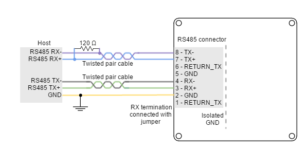
Next figure illustrates how to connect Jupiter Servo Drive with a host in a point to point configuration.
Termination resistor
The use of termination resistors at the RX side of each differential pair (120 Ω between RX+ and RX- of both host and slave) is essential for correct operation of the RS485 communication. For long cable distances (> 10 m) a termination in the TX side is also recommended.
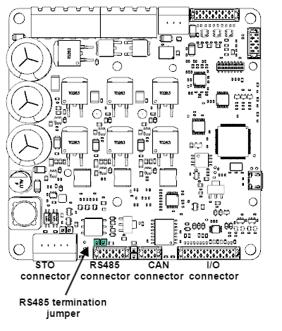
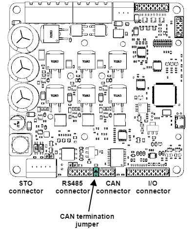
Jupiter Servo Drive includes a RX termination resistor on board. A jumper placed above the RS485 connector allows the user to terminate the bus with a 120 Ω resistor. Use a standard 2.54 mm pitch jumper for this purpose.
Another 120 Ω termination resistor should be placed at the end of Jupiter TX line (RX of the host). Suggested termination resistor: Xicon 271-120-RC.
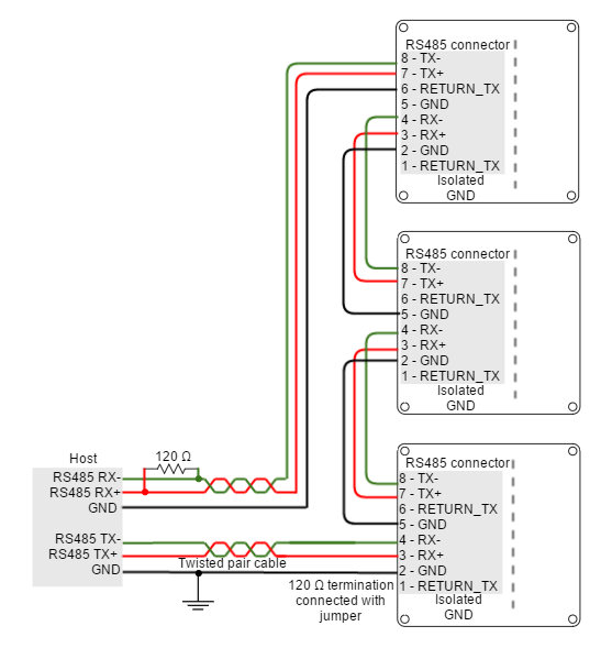
Multi-point connection using daisy chain
Daisy chain connection is a multi-point network topology based on connecting multiple terminals in a ring. The wiring consists on connecting the TX terminals of each device to the RX terminals of the next device. An example of daisy chain wiring of multiple Jupiter is shown in the next figure.
Termination resistor for daisy chain
In daisy chain connection, termination resistors are required in each link. For short distances, a 120 Ω termination resistor in the RX side is required. For long distances (> 10 m) a termination is required in RX and TX sides.
Jupiter includes a termination on the RX line (activated through a jumper) allowing direct daisy chain wiring for short links.
RS232 interface
Jupiter Servo Drive is provided with RS485 interface, but can be supplied with RS232 isolated interface. Please, contact with Ingenia to purchase Jupiter Servo Drive with RS232.
Following table shows some specifications of the Jupiter RS232 interface:
Specification | Details |
|---|---|
| Interface | Isolated (2.5 kVRMS) Self-supplied (no need for external supply) Simplex, half-duplex and full-duplex |
| Baud rate | 9600 bps to 115200 bps (default value) |
| Communication distance | Up to 15 m |
Daisy chain | Supported |
RS485 jumper in RS232 interface
If the RS485 termination jumper is closed in the Jupiter Servo Drive with RS232 interface, RS232 communication will not work!
RS232 application
RS232 interface is only recommended for configuration purposes. For noisy environments, CANopen interface is strongly recommended.
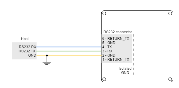
Next figure illustrates how to connect Jupiter Servo Drive with a host in a point to point configuration.
Multi-point connection
Jupiter Servo Drive RS232 interface allow multi-point connection using daisy chain connection.
Multiple drive connection with daisy chain must be configured using Ingenia MotionLab2 suite. Please, see UART configuration section in E-Core documentation for further information.
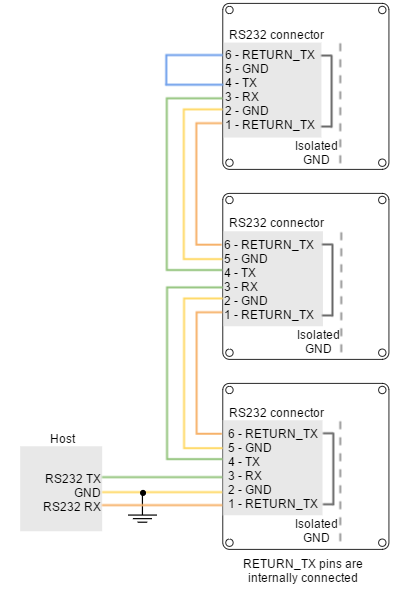
Multi-point connection using daisy chain
Daisy chain connection is a multi-point network topology based on connecting multiple terminals in a ring. The wiring consists on connecting the TX terminal of each device to the RX terminal of the next device. With the use of RETURN_TX terminal (which directly connects terminals 1 and 6) daisy chain wiring can be simplified. An example of RS232 daisy chain wiring is shown in the next figure.
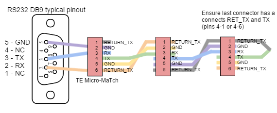
Daisy chain clever wiring with flat cable
The Jupiter Servo Drive RS232 connector allows to implement a daisy chain using 6 way 1.27 pitch flat ribbon cable. This solution highly simplifies the wiring.
The use of RETURN_TX pin simplifies the wiring and maximizes EMI immunity due to minimum ground loop and close returns for TX and RX.
To implement an RS232 daisy chain cable follow next steps:
- Crimp the first connector in the ribbon cable.
- Cut lines 1, 2 and 3 (RETURN_TX, GND, RX).
- Twist the cable once and connect lines 4, 5 and 6 (TX, GND, RETURN_TX) to pins 1, 2 and 3 to the next connector.
- Repeat until the last device
- On the last device, connect TX and RETURN_TX (lines 4-1 or 4-6).
RS232 wiring recommendations
Although RS232 is a widespread communication standard it has some disadvantages when operating in noisy environments. Following are some wiring recommendations.
- Use 3-wire shielded cable with the shield connected to Jupiter Servo Drive end. Do not use the shield as GND. The ground wire must be included inside the shield, like the RX and TX signals.
- Do not rely on an earthed PC to provide the Jupiter Servo Drive earth connection. The drive must be earthed through a separate circuit. Most communication problems are caused by the lack of such connection.
- Ensure that the shield of the cable is connected to the shield of the connector used for communications.
- Avoid creating ground loops.
- Shortest cables are preferred
CANopen interface
Jupiter Servo Drive supports CANopen interface, a multi-terminal communication protocol based on CAN (Controller Area Network) bus. Jupiter CAN interface is isolated, and self-supplied. Main physical specifications are shown in the next table:
Specification | Details |
|---|---|
| Interface | Isolated (2.5 kVRMS) Self-supplied (no need for external supply) |
Baud rate | From 125 kbps to 1 Mbps (default value) |
Maximum number of nodes | 64 |
Common mode voltage | Up to 48 V |
| Termination resistor | 120 Ω on board (mount jumper to enable the termination) |
Drive ID
When installing CANopen communication, ensure that each servo drive is allocated a unique ID. Otherwise, CANopen network may hang.
An example of CAN wiring is shown in the next figure.
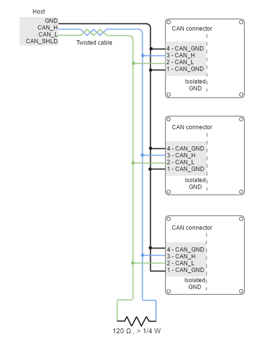
Termination resistor
The use of bus termination resistors (120 Ω between CAN_L and CAN_H), one at each end of the bus, is essential for correct operation of the CAN bus. Even with only one Jupiter connected, mount the termination resistor to ensure CAN bus operation. Do not use wirewound resistors, which are inductive.
Jupiter Servo Drive includes a termination resistor on board. A jumper placed next to the CAN connector allows the user to terminate the bus with a 120 Ω resistor. Use a standard 2.54 mm pitch jumper for this purpose.
CAN GND connection
GND line in CAN devices is used for equaling potential between master and slaves, but is not used for data transmission, as the line is fully differential. However, since Jupiter CAN interface is fully isolated, it is strongly suggested to connect the CAN_GND pin to the CAN bus cable SHIELD to maximize CAN bus noise immunity.
If power flat ribbon cable is used, it is preferred to connect both GND connector pins (1 and 4), equaling the signal to GND impedance.
CAN interface for PC
The Ingenia MotionLab2 suite is able to communicate with the Jupiter Servo Drive through CANopen interface. For this purpose, a CAN transceiver for PC is required. Motion Lab is compatible with the following CAN transceivers: Kvaser, Peak-System, IXXAT, Vector and Lawicel. Please, install the drivers you can find on the manufacturer web sites before, plugging any transceiver to the USB port. Execute Motion Lab only after the device is already installed.
Some recommended CAN transceivers are shown below:
| Manufacturer | Part Number | Description |
|---|---|---|
| Peak-system | PCAN-USB opto-decoupled (IPEH-002022) |
|
| Kvaser | USBcan Pro 2xHS v2 |
|
| IXXAT | USB-to-CAN V2 Professional |
|
| Vector Informatik | VN1630 |
|
CAN wiring recommendations
- Build CAN network using cables with 2-pairs of twisted wires (2 wires/pair) as follows: one pair for CAN_H with CAN_L and the other pair for CAN_V+ with CAN_GND.
- Cable impedance must have an impedance of 105 to 135 Ω (120 Ω typical) and a capacitance below 30 pF/meter.
- Whenever possible, use bus links between the CAN nodes. Avoid using stubs (a "T" connection, where a derivation is taken from the main bus). If stubs cannot be avoided keep them as short as possible. For maximum speed (1 Mbps), use a stub length lower than 0.3 meters.
- For a total CAN bus length over 40 meters, it is mandatory to use shielded twisted cables. Connect the cable shield to protective earth at both ends. Ensure that the cable shield is connected to the connector shield, as connection to host protective earth is usually soldered inside the connector.
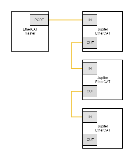
EtherCAT interface
Jupiter Servo Drive with EtherCAT (JUP-x/xx-E) provides access to the EtherCAT fieldbus system. EtherCAT is an isolated bus suitable for hard and soft real-time requirements in automation technology, test and measurement and many other applications.
Next table summarizes the features of the Jupiter EtherCAT interface.
| EtherCAT specific features | |
|---|---|
Ports available | 2 |
| LED Signals | Status LED |
| Link/Act LED | |
Supported Mailbox | CoE |
SDO info | Not supported |
Segmented SDO | Supported |
SDO complete access | Not supported |
| Synchronization modes | Free Run |
Distributed clock (Cyclic modes) | |
| Process data object | Configurable, up to 64 objects |