Feedback connections
The Jupiter Servo Drive has a feedback connector and an absolute encoder connector dedicated to the following feedback options:
- Digital Halls
- Analog Halls
- Quad. Incremental encoder
- Analog encoder (Sin-Cos encoder)
- Absolute encoder
Additional feedback connections can be found on I/O connector:
Jupiter also provides a 5V, 200 mA outputs for feedbacks supply. This output is overload and short circuit protected.
Digital Halls interface
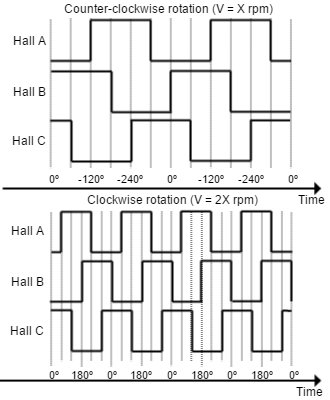
The Hall sensors are Hall effect devices that are built into the motor to detect the position of the rotor magnetic field. Usually, motors include 3 hall sensors, spaced 120º apart. Using these 3 signals, the drive is capable to detect the position, direction and velocity of the rotor. Next figures show examples of digital halls signals.
Digital halls signals example |
|---|
|
Digital halls can be used for commutation, position and velocity control. Resolution using these sensors is much lower than using encoders. Jupiter can use single ended Hall sensors to drive the motor with trapezoidal commutation, but not with sinusoidal commutation.
This interface accepts 0-5 V level input signals. Inputs are pulled up to 5 V, so industry standard open collector and logic output hall effect sensors can be connected. Next table summarizes digital halls inputs main features:
Specification | Value |
|---|---|
Type of inputs | Non-isolated |
Number of inputs | 3 |
ESD capability | IEC 61000-4-2 (ESD) ± 15 kV (air), ± 8 kV (contact) |
Voltage range | 0 ~ 5 V |
| Maximum voltage range | -0.5 ~ 5.5 V |
| Maximum recommended working frequency | 1 kHz |
1st order filter cutting frequency (-3dB) | 160 kHz |
| Sampling frequency | 10 ksps |
Type of sensors | Open collector |
| Pull-up resistor value | 1 kΩ (The pull-up is activated only when the drive is configured to use digital hall sensors) |
Digital and analog Halls
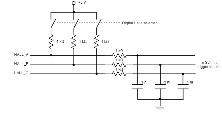
Digital halls input ports are shared with Analog Halls interface pins.
The 1 kΩ pull-up resistors are disconnected when Analog-halls input is selected to prevent analog data corruption.
Next figure shows the circuit model of the digital Halls inputs.
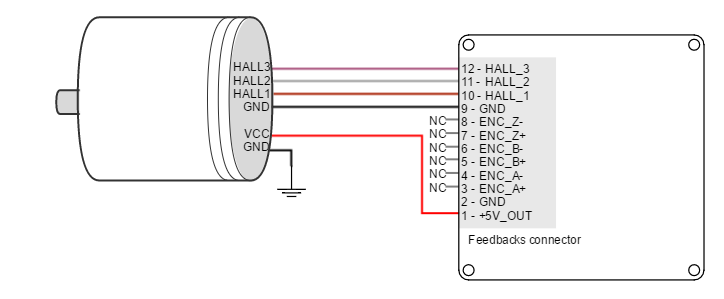
Next figure illustrates how to connect the digital halls to the Jupiter Servo Drive. Refer to Feedback wiring recommendations for more information about connections and wires.
Velocity control
Due to inherent low resolution of motor mounted Hall sensors, they are not recommended for velocity feedback in low speed applications.
Analog Halls interface
The Jupiter Servo Drive can operate with analog Hall sensors (also known as linear halls) as feedback option. Signals provided by these sensors are typically 5 V peak-to-peak sinusoidal signals, with 2.5 V offset and a phase shift of 120 degrees. These sensors can be used for a fine positioning of the rotor. Jupiter analog halls inputs main features are shown in next table:
Specification | Value |
|---|---|
Type of inputs | Non-isolated |
Number of inputs | 3 |
ESD capability | IEC 61000-4-2 (ESD) ± 15 kV (air), ± 8 kV (contact) |
| Maximum recommended working frequency | 1 kHz |
2nd order filter cutting frequency | 10.8 kHz |
| Sampling frequency | 10 ksps |
Voltage range | 0 ~ 5 V (10 bits) |
| Maximum voltage range | -0.3 ~ 5.3 V |
| Input impedance | > 24 kΩ |
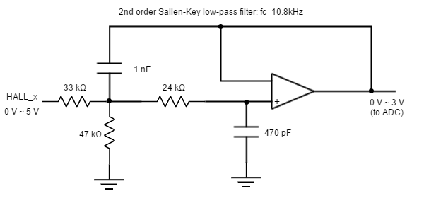
Next figure illustrates the circuit model for one of the linear Halls inputs. An active Sallen-Key low pass filter provides immunity to motor and feedback noise. Note that analog halls pins are shared with Digital Halls interface, to avoid any signal distortion, when analog halls interface is selected, the 1 kΩ pull-up is disconnected automatically.
Next figure shows how to connect the linear Halls to the Jupiter Servo Drive. Refer to Feedback wiring recommendations for more information about connections and wires.

Digital Incremental Encoder
Jupiter can use single ended or differential digital incremental encoder inputs (also known as quadrature incremental encoders) for velocity and/or position control, as well as commutation sensor. The encoder provides incremental position feedback that can be extrapolated into precise velocity or position information. Using high resolution encoders allows Jupiter Servo Drive to use sinusoidal commutation.
Channel A and channel B signals should have a phase shift of 90 degrees, indicating the rotation direction. Based on the pulses frequency, the drive can calculate the motor velocity and position.
| Example of single ended digital encoder inputs | Example of digital differential encoder signals |
|---|---|
|
|


High precision applications
High resolution motor mounted encoders allows excellent velocity and position control at all speeds. Encoder feedback should be used for applications requiring precise and accurate velocity and position control. Digital encoders are especially useful in applications where low-speed smoothness is the objective.
The Jupiter Servo Drive has one differential digital encoder interface, with optional index signal input. Index signal (Z) is a single pulse per revolution signal that can be used to know absolute positions. Next table illustrates digital encoder inputs main features.
Specification | Value |
|---|---|
Type of inputs | Non-isolated |
Number of inputs | 3 (A, B and Index) |
ESD capability | IEC 61000-4-2 (ESD) ± 15 kV (air), ± 8 kV (contact) |
Nominal voltage range | 0 ~ 5 V |
Maximum voltage range | -0.5 ~ 5.5 V |
| Maximum recommended working frequency | 10 MHz (differential) |
1st order filter cutting frequency (-3 dB) | 6.6 MHz |
| Maximum readable pulse frequency | 30 MHz |
| Termination resistor | 120 Ω (between ENC_x+ and ENC_x-) |
| Bias resistors | ENC_x+ (positive input) 1 kΩ to 5 V ENC_x- (negative input) 1 kΩ to 2.5 V (equivalent) |
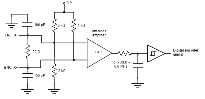
For encoder signal reception, an analog differential line receiver with an hysteresis comparator is used. The high signals (ENC_A+, ENC_B+ and ENC_Z+) are pulled up to +5 V, and the low signals (ENC_A-, ENC_B- and ENC_Z-) are biased to 2.5 V. This arrangement let user to connect either differential output encoders or single ended encoders (both open collector and totem pole).
The encoder interface also accepts an RS-422 differential quadrature line driver signal in the range of 0 V to 5 V, up to 10 MHz. When single ended encoder is connected, only high signals (ENC_A+, ENC_B+ and ENC_Z+) must be used.
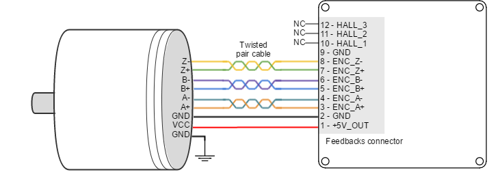
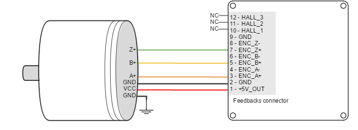
Next figures illustrate how to connect a differential and a single ended encoder to the Jupiter Servo Drive. Refer to Feedback wiring recommendations for more information about connections and wires.
Next figure shows the circuit model of the digital encoder inputs.
Digital encoders with single-ended 24 V / 12 V outputs
The Jupiter Servo Drive can also interface single-ended digital encoders with output voltages higher than 5 V. With the use of series-connected limiting resistors, Jupiter is able to read encoder counts correctly while the inputs are correctly protected. Use a resistor in series with the ENC_X- (inverting) input and leave the ENC_X+ floating. For 24 V encoders use a 4.7 kΩ 0.25 W resistor. For 12 V encoders use a 2.7 kΩ 0.1 W resistor.
Note that this additional resistance may limit the maximum encoder frequency to approximately 1 MHz by making a low pass filter with the 100 pF input capacitance.
An external power supply for the encoder will be necessary, ensure this power supply is referred to the same GND as the Jupiter.
Digital encoders with differential 24 V / 12 V outputs
To interface with 24 V push-pull style differential encoders, it is recommended to connect 4.7 kΩ 0.25 W resistors in series between the encoder signals and the corresponding drive inputs. For 12 V push-pull style differential encoders, use a 2.7 kΩ 0.1 W resistor.
This ensures a correct differential signal reading as well as limiting currents to safe levels. Note that this additional resistance may limit the maximum encoder frequency to approximately 1 MHz by making a low pass filter with the 100 pF input capacitance.
An external power supply for the encoder will be necessary, ensure this power supply is referred to the same GND as the Jupiter.
Encoder broken wire detection
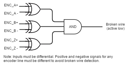
Jupiter Servo Drive includes a broken wire detection circuit. The circuit is based on 3 EX-OR gates that will generate an error if the encoder is disconnected or a wire is broken. This system only works for differential encoders.
Encoder without Index (Z) line
To avoid a broken wire fault when the differential encoder has no index (Z) line, connect the negative pin (ENC_Z-) to GND (this ensures the XOR result = 1) or configure the encoder as single ended in MotionLab.
Analog encoder (Sin-Cos encoder) interface
The Jupiter Servo Drive can use analog encoder (also known as Sin-Cos encoder) as position and velocity feedback element. This sensor provide a pair of quadrature sine and cosine signals as the motor moves, which frequency depends on the motor speed. The signals may be generated by optical or magnetic means. For noise immunity the signals are typically transmitted differentially from the encoder to the sensor interface electronics.
| Pin | Signal description | Signal example |
|---|---|---|
SIN+ | Sine wave with 2.5 V offset and 0.5 Vpp |  |
| SIN- | Same as SIN+, but with 180º phase shift | |
| COS+ | Cosine with 2.5 V offset and 0.5 Vpp | |
| COS- | Same as COS+, but with 180º phase shift | |
| REF+ / ZERO+ | One sine half wave per revolution as index pulse. | |
| REF- / ZERO- | Same as REF+, but with 180º phase shift |
Sin-Cos calibration
Analog encoder signals are not always perfect sine and cosines. For this reason, Jupiter includes sin-cos calibration and adjustment parameters. For further information see the E-Core registers for Sin-Cos encoder configuration.
An automatic calibration based on Lissajous curves is included in MotionLab, which allows an easy feedback adjustment.
Next table summarizes analog encoder inputs main features.
Specification | Value |
|---|---|
Type of inputs | Differential analog input (switching to digital automatically at high speed) |
Number of inputs | 3 (SIN, COS, REF) |
ESD capability | IEC 61000-4-2 (ESD) ± 15 kV (air), ± 8 kV (contact) |
| Typical voltage range | 2.25 ~ 2.75 V |
| Maximum voltage range | -0.5 ~ 5.5 V |
Maximum recommended working frequency | 1 kHz used as analog encoder 10 MHz used as digital encoder |
1st order filter cutting frequency (-3 dB) | 6.6 MHz |
| Sampling rate (analog) | 10 ksps |
| Maximum readable pulse frequency (digital) | 30 MHz |
Input impedance | 120 Ω resistive differential 100 pF capacitive 1 kΩ to GND |
Resolution | 10 bits |
Next figure shows how to connect a differential Sin-Cos encoder to Jupiter Servo Drive. Refer to Feedback wiring recommendations for more information about connections and wires.
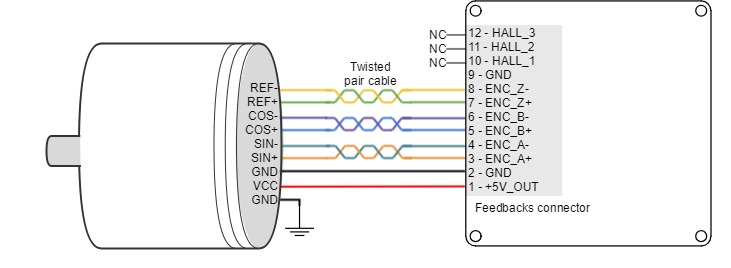
Circuit model for each differential channel (A, B, REF) is shown in the next figure.
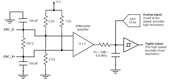
For differential Sin-Cos encoders with peak to peak voltage exceeding 1 Vpp it is recommended to use a series resistor on ENC_X+ and ENC_X- pins. The value of that resistor should be chosen to attenuate the voltage at the input around 1 Vpp ± 20%. Use the following formula to determine the resistor that must be placed on each input. Rin = 50 · ( Vinpp - 1 V). Example: for 3 Vpp Sin-Cos, the resistance in series with each pin should be Rin = 50 · (3 - 1) = 100 Ω.
If no REF (Or Zero index) signal is available leave the ENC_Z- and ENC_Z+ pins floating.
For single ended analog Sin-Cos encoders. Connect the encoder signals to the ENC_x+ (positive) inputs.
- If the average of the sine and cosine is 2.5 V±0.1 V. ENC_x- inputs should be left floating.
- If the average is different to 2.5 V±0.1 V. connect all the ENC_X- inputs to the average value. Some encoders provide this output and name (confusingly) Vref. The value of the average must be between 0.6 V and 4.4 V.
Absolute encoder interface
The Jupiter has an Absolute encoder connector that can be used as position and velocity feedback element. This sensor generates digital data that represent the encoder actual position. From the position information, speed and direction of motion is calculated. The position is not lost even if the encoder is powered down, this means it is not necessary to move to a reference position as with incremental type encoders.
Next table shows the absolute encoder inputs electrical specifications.
Specification | Value |
|---|---|
Type of inputs | Non-isolated |
ESD capability | IEC 61000-4-2 (ESD) ± 12 kV (air), ± 12 kV (contact) |
| Number of inputs | 2 (CLK and DATA) |
| Nominal voltage range | 0 ~ 5 V |
| Maximum voltage range | -13 ~ 16.5 V |
| Maximum readable frequency (SSI) | 1 kHz (standard Firmware) 10 kHz (SSI only firmware) |
| Termination | 120 Ω on data line |
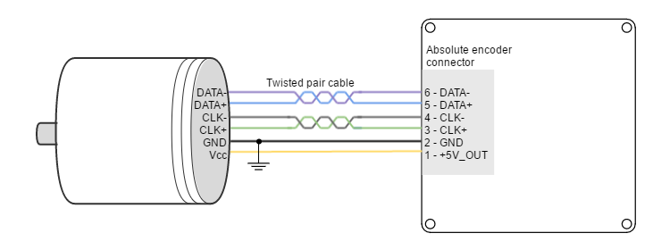
Next Figure shows how to connect an Absolute encoder to Jupiter Servo Drive. Refer to Feedback wiring recommendations for more information about connections and wires.
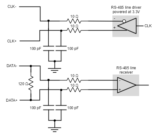
Circuit model for the absolute encoder receiver channels is shown in the next figure
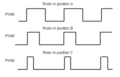
Digital input feedback - PWM encoder
Jupiter Servo Drive can also use a PWM encoder connected through the I/O connector as a feedback element. A PWM encoder provides a Pulse Width Modulated (PWM) signal with a duty cycle proportional to the angle (position) of the rotor. This feedback can be interfaced through the high-speed digital input 1 (HS_GPI1). Both differential and single-ended PWM encoders can be used. Further specifications about the PWM input can be found in I/O connection section.
Next figure illustrates PWM feedback input for different rotor positions:
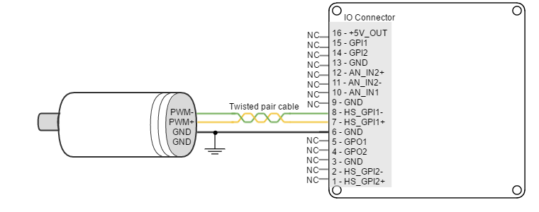
Next figure illustrates how to connect a differential PWM encoder to the Jupiter Servo Drive:
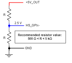
Single ended operation
In order to use the high-speed digital input in single ended mode, connect the negative terminal (HS_GPIx-) to 2.5 V. This voltage can be achieved with a voltage divider from +5V_OUT.
For a 24 V input, the negative terminal (HS_GPIx-) can be connected to 5 V (+5V_OUT).
Next figure illustrates how to connect a single ended PWM encoder to the Jupiter Servo Drive:
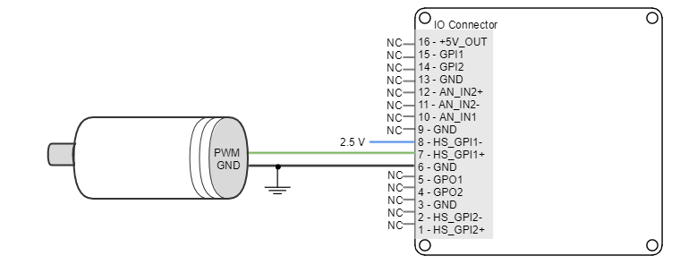
Refer to Feedback wiring recommendations for more information about connections and wires.
Analog input feedback
Jupiter Servo Drive can also use analog feedback systems connected through the I/O connector. From the voltage level of one analog input, the position or velocity of the rotor can be calculated. The Jupiter have 2 analog inputs that can be used for feedback input, each one with a different input range. The input used as feedback can be selected by software. Further specifications about the analog inputs input can be found in I/O connection section.
Refer to Feedback wiring recommendations for more information about connections and wires.
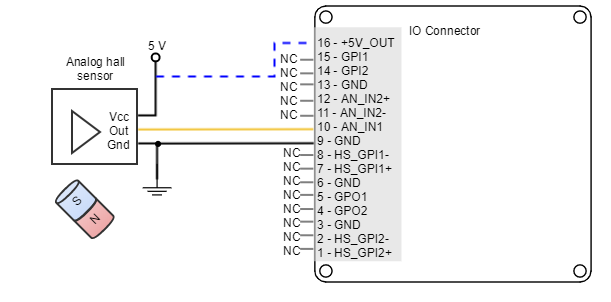
Analog hall input
A typical analog sensor used for position feedback is an analog hall sensor. This sensor provides a voltage proportional to the rotor position.
The following picture shows how to connect an analog hall sensor using analog input 1 (AN_IN1):
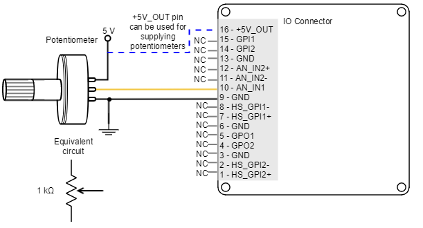
Potentiometer
A typical analog sensor used for position feedback is a potentiometer. This sensor provides a voltage proportional to the rotor position.
The following picture shows how to connect a potentiometer as a position sensor using analog input 1 (AN_IN1):
Recommended potentiometer resistance
Potentiometers with high values of resistance (> 10 kΩ) can result in non linear behavior due to its the drive parallel input resistors. High resistance values also reduce the signal to noise ratio, making it easier to have disturbances and reducing the quality of the measure.
However, a very small value of resistance may also consume too much power and cause self heating (which causes additional variations on resistance).
Therefore, use the smallest value of resistance that:
- Does not exceed 1/2 of the potentiometer power rating (to allow safety margin and prevent self heating).
- Does not exceed the +5V_OUT current capacity.
Typically 1 kΩ to 10 kΩ will be preferred.
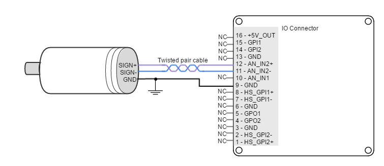
DC tachometer
The Jupiter Servo Drive can use a DC tachometer for velocity feedback through the I/O connector. A DC tachometer provides an analog signal whose voltage level is proportional to the rotor speed.
Next figure illustrates how to connect a DC tachometer with differential output to the Jupiter Servo Drive.
Feedback wiring recommendations
Signal distortion and electrical noise is a common problem in feedback signals. These problems can result in a bad position or velocity calculation for both digital feedbacks (gain or loss of counts) and analog feedbacks (wrong voltage levels).To minimize these problems some wiring recommendations are shown:
- Use differential signals whenever is possible. That is, connect both positive and negative signals of differential feedback sensors. Use a twisted pair for each differential group of signals and another twisted pair for the +5 V supply and GND. Twisted-pairs help in elimination of noise because disturbances induced in twisted pairs
- Twisted-pairs help in elimination of noise due to electromagnetic fields by twisting the two signal leads at regular intervals. Any induced disturbance in the wire will have the same magnitude and result in error cancellation.
- Connect the Jupiter and encoder GND signals even if the encoder supply is not provided by the drive.
- Connection between Jupiter PE and the motor metallic housing is essential to provide a low impedance path and minimize noise coupling to the feedback. For further information, see Protective Earth wiring.
- For better noise immunity, use shielded cables, with the shield connected to PE only in the drive side. Never use the shield as a conductor carrying a signal, for example as a ground line.
- It is essential to keep feedback wiring as far as possible from motor, AC power and all other power wiring.
Recommendations for applications with close feedback and motor lines
In some applications, like in the subsea market, where additional connectors and cables are a problem, the feedback cannot be wired separately from the motor and power lines. This creates noise problems that could result in hall sensors wrong commutation errors or encoder loss of counts. For these applications we recommend:
- Use a common mode choke on the motor phases. This single action can reduce common mode noise drastically and will solve most problems. See recommended wiring in Motor and shunt braking resistor wiring.
- Ensure the motor housing is well connected to protective earth and the system chassis (PE).
- If possible, minimize power supply voltage. This will also minimize the electromagnetic noise generated by the motor switching.
- Add additional RC low pass filters on the feedback inputs. The filter should attenuate at a frequency above the maximum speed signal to prevent loss of counts and signal distortion. Preferably use resistors with low values to prevent distortion to the servo drive input circuit at low frequency (< 500 Ω). Use ceramic capacitors with good quality dielectric, like C0G.