Power supply
Low current versions of Jupiter Servo Drive (JUP-20/80-y and JUP-15/130-y) are supplied from the Supply and shunt connector. High current versions of Jupiter (JUP-40/80-y and JUP-30/130-y) are supplied from the the Supply, shunt and motor connector. Both versions have separated supply inputs for the logic and the power stage. An internal DC/DC converter provides circuits with appropriate voltages as well as a regulated 5 V output voltage to supply feedback sensors and I/O.
The Jupiter can be powered from USB for configuration purposes without the need of an external power supply. An internal switch automatically chooses the power source prioritizing the external supply. Please note that several functionalities will not be available when powered from USB.
USB Powered Jupiter
When the Jupiter is powered from USB, only basic configuration and programming options are available. The drive is not capable of driving a motor or sensing a feedback input due to USB power limitations.
Disconnection recommendations
There are no critical instructions for disconnecting the Jupiter. Just some recommendations:
- The board could be hot during < 1 min after disconnection.
- Preferably do not disconnect the supply while having a motor in motion.
- If working with Motion Lab with USB connection, preferably disconnect the drive from the application before disconnecting. This prevents COM port corruption.
Power supply requirements
The choice of a power supply is mainly determined by voltage and current ratings of the power supply. Main requirements of the Jupiter power supply are:
- The voltage should be the targeted for the motor. This means up to 80 V for the JUP-X/80 and up to 130 V for the JUP-X/130. Make sure that the voltage of the power supply does not exceed this maximum including tolerances and regulation, some power supplies tend to have voltage overshoot during sudden current changes or at startup.
- The current should be the one able to provide the phase peak current of the application. This means up to 40 A for the JUP-20/80, 80 A for the JUP-40/80, 30 A for the JUP-15/130 and up to 60 A for the JUP-30/130. Make sure that the current rating for the power supply is at least as high as the motor.
- The voltage and current range can be decreased due to the motor requirements.
Although the logic supply accepts a wide voltage range, a power supply of 24 V and 5 W is recommended.
Further information on how to dimension a power supply for the Ingenia drives can be found here.
Following are shown different power supply examples:
Manufacturer | Part Number | Rated Voltage (V) | Rated Current (A) | Image | Description |
|---|---|---|---|---|---|
| CUI Inc. | VSK-S5-24UA-T | 24 | 230 mA |
| Enclosed linear power supply for all Jupiter variants logic supply. |
| CAMTEC Power Supplies | CPS-EX3000.072 | 72 | 41.6 |
| Switching power supply recommended for Jupiter-xx/80, 3000 W |
| CAMTEC Power Supplies | CPS-EX3000.110 | 110 | 27.2 |
| Switching adjustable power supply recommended for Jupiter-xx/130, 300 W |
| Keysight Technologies | N8740A | 150 | 22 | Switching multi-range power supply recommended for Jupiter-15/130, 3300 W |


Inrush current
During power up a short duration high current peak is needed to charge the drive internal DC bus capacitors (see specification page to know the value of the capacitors), this is called inrush current. This current will only be limited by the power supply, the wiring and connectors resistance, the drive reverse polarity protection resistance (~ 65 mΩ) and the bus capacitance equivalent series resistance (ESR ~ 5 mΩ).
Since power supplies have a power-up ramp (or soft start) this typically does not represent a problem at all. However in systems with many axis in parallel or when the DC supply is controlled by a relay, an inrush current limit circuit is strongly suggested, otherwise, the peak can cause unnecessary stress to the power supply and electronics that could reduce its lifespan. There are 2 common ways to solve this.
- Use a passive Inrush Current Limiter (ICL). Which is a negative temperature coefficient (NTC) resistor showing a high resistance at startup that limits the peak and then drops down during operation. This option provides the lowest cost and simplicity but will become hot during operation and reduce system energy efficiency. Choose according to your system current ratings and power supply capacity.
- Use an active precharge relay circuit. By having a current limit resistor between power supply that will limit the inrush and then bypass it with a electromechanical or solid state relay. Some relays include an on-delay function. An alternative is to activate the relay from the driver after power up, by using a macro and a GPO to control the relay.
Power supply connection
Jupiter logic and power supplies are provided through two different pins, LOGIC_SUP and POW_SUP. Therefore, the logic circuitry and the power stage can be powered from different power supplies.
- Jupiter versions JUP-20/80 and JUP-40/80 support +10 V to +80 V in both inputs.
- Jupiter versions JUP-15/130 and JUP-30/130 support +10 V to +90 V in the LOGIC_SUP input, and +10 V to +130 V in the POW_SUP input. In the 130V version the bypass diode from DC bus is not mounted.
Twisted cables
Twisted power supply cables are preferred to reduce electromagnetic emissions and increase immunity.
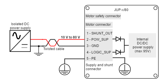
The following pictures show the Jupiter versions JUP-20/80 and JUP-40/80 supply wiring diagrams. These versions can be supplied using only the POW_SUP input or using separated power supplies for POW_SUP and LOGIC_SUP. This method is interesting to avoid loosing communication with the Jupiter in case of POW_SUP failure.

Double supplied Jupiter
In Jupiter versions JUP-20/80 and JUP-40/80, if POW_SUP voltage is higher than LOGIC_SUP voltage, the logic circuitry is powered from the POW_SUP supply. An internal diode connects the DC bus with the logic supply.
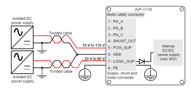
The following picture shows the Jupiter versions JUP-15/130 and JUP-30/130 supply wiring diagram. Note that a separate power supply is required above 90 V.
Isolated power supplies
For safety reasons, it is important to use power supplies with full galvanic isolation.
Battery connection
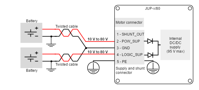
Next figure shows a simplified wiring diagram for the JUP-20/80 and JUP-40/80 versions supplied from a battery.
Next figure shows a simplified wiring diagram for the JUP-15/130 and JUP-30/130 versions supplied from a battery.
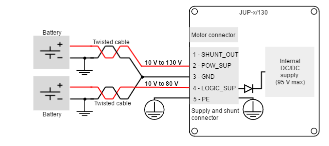
Motor braking current
Motor braking can cause reverse current sense and charge the battery.
Always ensure that the battery can accept this charge current which will be within the Jupiter current ratings.
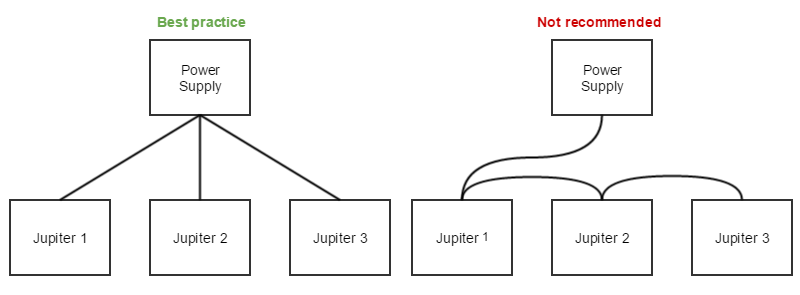
Connection of multiple drives with the same power supply
When different servo drives are connected to the same power supply, connect them in star topology for reducing cable impedance and common mode coupled noise. That is, connect each drive to the common supply using separate wires for positive and return.
Power supply wiring recommendations
Wire section
The minimum wire section is determined by the current consumption and the allowed voltage drop across the conductor. It is preferred to use wide section stranded wires to reduce impedance, power losses and ease the assembly. Insulator size should not exceed connector pitch
- For JUP-20/80 and JUP-15/170, insulator size should not exceed 5 mm.
- For JUP-40/80 and JUP-30/170, insulator size should not exceed 6.35 mm.
Following table indicates recommended section for JUP-20/80 and JUP-15/170:
| Connection | Minimum wire size | Maximum wire size |
|---|---|---|
| Stranded wire (preferred) | 1.5 mm2 (15 AWG) | 4 mm2 (12 AWG) |
| Solid wire | 1.5 mm2 (15 AWG) | 4 mm2 (12 AWG) |
Following table indicates recommended section for JUP-40/80 and JUP-30/170:
| Connection | Minimum wire size | Maximum wire size |
|---|---|---|
| Stranded wire (preferred) | 2 mm2 (14 AWG) | 4 mm2 (12 AWG) |
| Solid wire | 3 mm2 (12 AWG) | 6 mm2 (10 AWG) |
Wire ferrules
For low power applications, it is recommended to use wire ferrules to prevent cable damage or wrong contacts. For higher power applications, direct cable connection is recommended, since it provides lower contact resistance.
Due to connector's size, ferrule size is limited. For the JUP-20/80 and JUP-15/170 versions the maximum allowed ferrule size is 3 mm2. Ensure the insulator is does not exceed 5 mm (connector pitch). Following are some suggested ferrules for JUP-20/80 and JUP-15/170:


Due to connector's size, ferrule size is limited. For the JUP-40/80 and JUP-30/170 versions the maximum allowed ferrule size is 4 mm2. Ensure the insulator is does not exceed 6.35 mm (connector pitch). Following are some suggested ferrules for JUP-40/80 and JUP-30/170:
Manufacturer | Part number | Image | Description |
|---|---|---|---|
| Phoenix Contact |
| 4 mm2 (12 AWG) |

Wire length
- The distance between the Jupiter Servo Drive and the power supply should be minimized when possible. Short cables are preferred since they reduce power losses as well as electromagnetic emissions and immunity.
- For best immunity use twisted and shielded 2-wire cables for the DC power supply. This becomes crucial in long cable applications.
- Avoid running supply wires in parallel with other wires for long distances, especially feedback and signal wires.