Protective earth
Connection of Jupiter Servo Drive and motor housing to Protective Earth (PE) is required for safety reasons. Electrical faults can electrically charge the housing of the motor or cabinet, increasing the risk of electrical shocks. A proper connection to PE derives the charge to Earth, activating the installation safety systems (differential protections) and protecting the users.
Moreover, a proper connection to PE prevents many of the electromagnetic compatibility (EMC) problems that occur operating a servo drive. Please check this document Electromagnetic Interference Issues With Servo Drive Systems.
Reducing EMI susceptibility
Connecting the drive PE terminals and cold plate screws to your system Earth and to the motor housing solves many noise and EMI problems. The PE drive terminals are decoupled to power ground through a safety capacitor. This provides a low impedance preferential path for coupled common-mode noises that otherwise would be coupled to sensitive electronics like the encoders. A good grounding of the drive to the earth of the power supply is also essential for a EMI reduction.
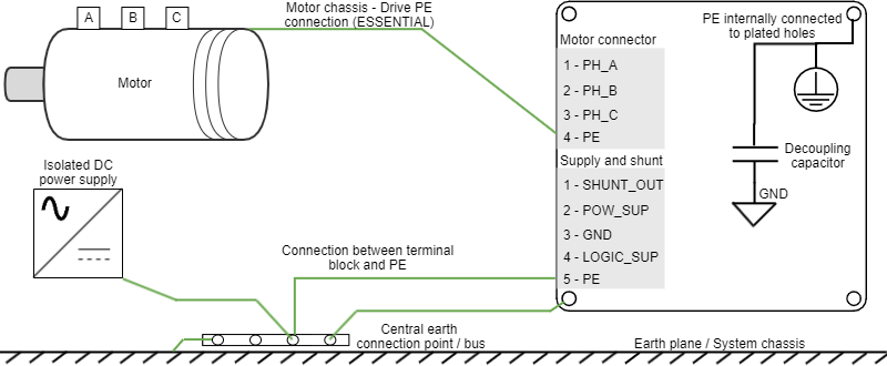
Jupiter Servo Drive provides the following earth/ground connection points, which are internally connected and decoupled to power ground, logic supply, and power supply:
- PE terminal in the Supply and shunt connector (only in JUP-20/80-y and JUP-15/170-y).
- PE terminal in the Motor connector (only in JUP-20/80-y and JUP-15/170-y).
- PE terminal in the Supply, shunt and motor connector (only in JUP-40/80-y and JUP-30/170-y).
- Plate holes. Note that this connection may not be reliable as the plate is anodized and conduction is not ensured. It is recommended to use grounding washers that scratch the anodizing and previously remove the anodizing on the contact area. Always ensure there is an additional PE connection using the terminal block.
A diagram of the recommended Earth wiring is shown following.
Earth plane reference
While some systems will not have a "real Earth" connection, use your machine chassis, the metallic structure of the device or a good grounding conductive plane as your reference earth.
Some considerations for a proper earth connection are detailed next:
- Switching noise can be coupled to the earth through the housing of the motor. This high-frequency noise creates a common mode current loop between drive and motor. Although the motor housing is connected to earth through the system chassis, its electrical connection may have a relatively high impedance and present a big loop. For this reason, is essential to reduce the common-mode current return path impedance and its loop area.
- For reducing the return path impedance, the motor frame should be directly wired to drive PE terminals.
- PE wiring should be as close as possible to power cables, reducing current loop.
- Power supply is another source of switching noise. The neutral of the grid transformer or the housing of our power supply may also be connected to earth. For reducing noise and EMI, similar considerations should be taken.
- Directly wire power supply PE to drive PE.
- PE wiring should be as close as possible to power supply cables.
- In order to avoid ground loops, it is a good practice to have a central earth connection point (or bus) for all the electronics of the same bench. If multiple drives are supplied from the same power supply or supply PE to drive PE connection is not practical (not enough connection terminals) connect all PE terminals in a central connection bus.
- Whenever possible, mount the Ingenia drive on a metallic conductive surface connected to earth. Use good quality plated screws that won’t oxidize or lose conductivity during the expected lifetime. Note that the PE terminal is internally connected with the Jupiter Servo Drive standoffs.
- For achieving low impedance connections, use wires that are short, thick, multistrand cables or preferably conductive planes. PE wire section should be, at least, the same as power supply cables. Always minimize PE connection length.
For an even better EMI immunity, use shielded or armored cables with isolating jacket, connecting the shield to PE with a cable clamp.
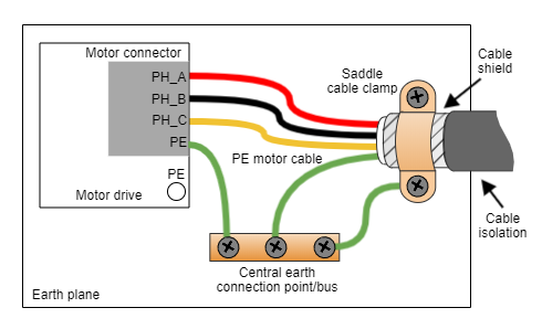
If simplified wiring is required, the following shielding priority can be applied:
- Shield the motor cables, which are the main high-frequency noise source.
- Shield the feedback signals, which are sensitive signals usually coming from the motor housing.
- Shield I/O signals and communication cables.
The clamp has to be selected according to the shielded cable diameter, ensuring good support and connection between the cable shield and the clamp. Following examples are only suggested for a conceptual purpose:
| Description | Image | Part number |
|---|---|---|
| Cable Clamp, P-Type Silver Fastener 0.625" (15.88 mm) |
| Keystone Electronics 8107 |
| Cable Clamp, P-Type Silver Fastener 0.187" (4.75 mm) |
| Keystone Electronics 8100 |
| Cable Clamp, Saddle Type Stainless Steel 20 mm |
| RS Pro 471-1300 |


