Safe Torque Off (STO), motor temperature and brake wiring
Jupiter Servo Drive includes some safety systems that are controlled externally. The safety systems are grouped as the Safe Torque Off (STO) and the motor safety systems.
Safe Torque Off (STO)
The STO is a safety system that prevents motor torque in an emergency event while Jupiter remains connected to the power supply. When STO is activated, the power stage is disabled automatically (no mater what control or firmware does), and the motor shaft will slow down until it stops under its own inertia and frictional forces.
The Jupiter STO works with negative logic, deactivating the power stage by default. In order to activate the power stage, and therefore allow the motor operation, two differential inputs must energized. These inputs activate two optocouplers connected in series that enable the Jupiter power stage operation. On the contrary, if the STO inputs are not energized, the transistors of the power stage are turned off and a STO fault is notified. During this state, no torque will be applied to the motor no matter configuration, or state of a command source. This will slow down the motor shaft until it stops under its own inertia and frictional forces. This input should not be confused with a digital input configured as enable input, because enable input is firmware controlled and does not guarantee intrinsic safety as it can be reconfigured by a user.
STO firmware notification
An STO stop is notified to the control DSP and creates a fault that can be read externally, however its performance is totally independent from control or firmware. When the STO is not connected it is virtually impossible to apply power to the drive.
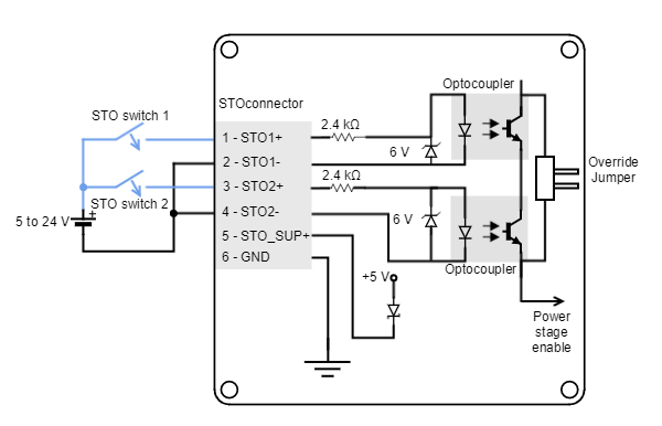
STO inputs have an input voltage range from +4.5 V to +24 V. In order to simplify the wiring, the STO connector includes a 5V (STO_SUP+) and GND pins. Next figure shows how to connect the STO inputs with an external power supply, although STO_SUP+ pin could be used.
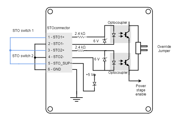
If STO option will not be used, it can be override with a jumper or simply connect the inputs without a switch, as can be seen in the following figure:
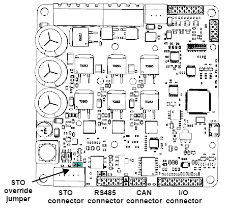
Overriding STO
In applications where the STO will not be used, this function can be disabled with a jumper that overrides the optocouplers. The jumper is situated besides the STO connector.
Motor safety systems connection
The Jupiter Servo Drive has a dedicated connector for motor safety systems. These safety systems consist on an external temperature sensor for the motor and an electromagnetic / electromechanical brake.
Motor brake
Electromechanical brakes are needed in critical applications where the disconnection of the motor or a lack of electric braking could be dangerous or harmful (i.e. falling suspended loads). Jupiter Servo Drive includes a brake output in the Motor safety connector to that end. This output consists on an open drain MOSFET (1 A full temperature range) and an additional Vbus terminal.
Brake or additional output
The brake output of the Jupiter is indeed a general purpose output (GPO5). It should be configured accordingly using MotionLab. Note that this output can also be used to drive high power loads. This can be easily configured using Motion Lab.
Next figure show how the typical connection using the main supply as brake power supply.
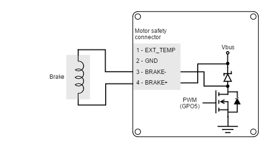
Brake connection using the main power supply
The on board supply connection is useful when:
- The brake nominal voltage is the same than the power supply voltage
- The brake nominal voltage is lower than the power supply voltage. In this case, the brake output voltage can be easily configured via the GPO5 PWM duty cycle.
Although effective brake voltage will be reduced by the PWM, ensure the brake withstands the peak voltage.
The Jupiter brake input can also be used with an external power supply, as shown in the next figure.
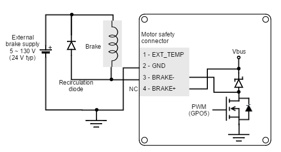
Brake connection using an external power supply
The external supply connection must be used when the brake nominal voltage is higher than the power supply voltage.
Free-wheeling diode
An internal freewheeling diode in anti-parallel with the brake is provided on board. This will prevent inductive kicking (voltage rise when current through the inductor falls to zero). However, the internal freewheeling diode is only applied when using the main power supply.
For external power supplies, an additional diode should be placed. Standard rectifier diodes such as 1N4002 or 1N4934 are appropriate for the application.
Brake operation details
The brake output is an N-Channel MOSFET internally connected to GPO5. Its operation is usually configured for normally locked electromechanical brakes; that is, brakes that by default block the movement of the motor shaft. For this reason, the switch is controlled with inverted logic, being activated to allow the rotation of the shaft. This kind of brakes increase the safety of the application, because in a drive power failure, the switch would be opened therefore the brake activated.
Main ratings of the brake switch are detailed in the next table:
Specification | Value |
|---|---|
Type of output | N-Channel MOSFET |
Maximum voltage | 130 V |
Maximum current | 1A (full tempeature range) |
Timing | Max activation / deactivation delay 50 µs Frequency PWM 20 kHz |
Protection | Overload and short circuit |
Turn-on and turn-off times
Turn-on and turn-off times are specified for loads at 24 Vdc and 700 mA. Turn-on and turn-off times are defined as the time to reach 95% of nominal current. The real time required for mechanical braking will strongly depend on the brake model and its dynamic behavior.
External temperature sensor wiring
The Jupiter motor safety system connector allows the connection of an external temperature sensor based on changes of resistance (PTC thermistor, bimetal, NTC, PT100, silicon temperature sensors) to measure the motor temperature. This analog input includes a pull-up for directly connecting a PTC thermistor as shown in the following figure:
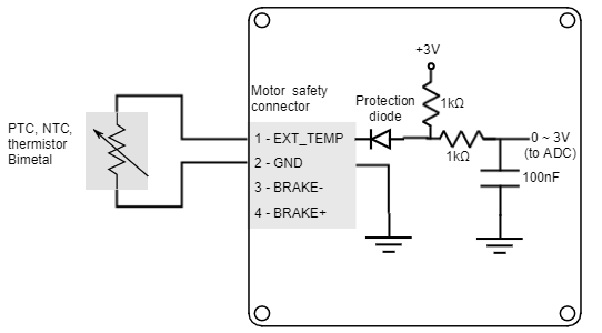
In order to correctly dimension the overtemperature levels it is suggested to use this calculator tool: https://jscalc.io/calc/N95gZmuUJr3tGAx1
Suggested PTC
The suggested PTC thermistor value is a 1 kΩ nominal resistance (@ 25 ªC) as Vishay PTC (TFPTL10L1001FL2B).
Main specifications of the external temperature sensor input are shown in the next table:
Specification | Value |
|---|---|
Type of input | Single ended analog |
ESD protection | 1000 V (Human Body Model) |