SinCos Encoder
SinCos encoders are angular encoders that modulate the shaft motion in the absence/presence and the frequency of two analog sine signals in quadrature (hence a sine and a cosine). In spite of the nuisance that supposes not working on digital signals directly for the controlling element, the fact that the signals have a continous range of values allows the controller to obtain an arbitrary level of resolution on the measurement, hence compensating the additional computational costs with improved resolution.
This view allows to configure the 1 Vp-p Sin/Cos parameters (also known as Analog Encoder).
| Parameter | Description |
|---|---|
| Sensor resolution | For rotary motors it is expressed in cycles / revolution, for linear motors it is expressed in nm. It is possible to enter decimal numbers in this field. |
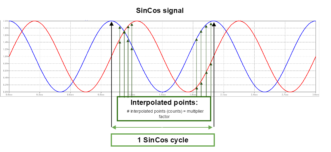
| Multiplier factor | Defines the interpolation factor applied to sensor. When the multiplied factor is available, the position resolution is increased as: We don't have a way to export this macro.
The minimum interpolation factor value is 2 and the maximum 10. |
| Total resolution | It is automatically calculated from the parameters above. For rotary motors it is expressed in "counts / revolution", for linear brushless motors it is expressed in "counts / magnetic pole pitch" and for the rest of linear motors it is expressed in "counts / stroke"; therefore it is very important to have the Magnetic Pole Pitch / Stroke properly configured. |
| Polarity | This parameter defines the positive sense of movement based on encoder. Use the Auto identify wizard to detect it. The main steps of the wizard are:
|
Advanced Settings
Sometimes the SinCos encoders produce minor signal anomalies or inaccuracies, due to manufacturing deviations and other causes. The advanced settings of SinCos view all allows to compensate that effect by adjusting the gain and offset of the two channels.
There is an auto-calibration wizard that automatically adjust these values. The main steps of the wizard are:
- Set a rated voltage percentage to be applied to the motor to move it and collect SinCos encoder data.
- Start the calibration test. This will move the motor to collect data, apply and algorithm to calculate the new gains and offsets values and finally move the motor again to verify the calculated values.
- A message is displayed showing the result of the test. If the test ends successful, the suggested values are displayed in a grid. If the test fails, a message is displayed giving information about the failure and how to fix it by modifying the parameters in Step 1.
Quick Test
The quick test monitors in real time the encoder position read, according to actual SinCos encoder configuration and user units selected.