Velocity control
This view shows the velocity control blocks and allows to manually configure the values of the velocity control schema.
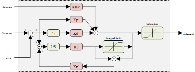
The filter implemented in the velocity control loop is a parallel PID with acceleration feedforward and also with antiwindup control.
Parameters of the control loop are as follow:
| Parameter | Description |
|---|---|
| Proportional gain | Proportional constant |
| Integral gain | Integral constant |
| Derivative gain | Derivative constant |
| Integral AW gain | Integral antiwindup constant |
| Acceleration FF gain | Acceleration feedforward constant |
| Integral limit | The output contribution of the integral term could be controlled by using the Integral Limit factor and the Antiwindup contant. This mechanism is useful to reduce the overshoot or response time of the system. In situations where the position demanded is not physically reachable or the torque is saturated, the contribution of the integral term will increase continuously as the position error will never be zero. When the error direction is reversed, due to a position demand change or after an overshoot correction, the control loop will require some time to react as the accumulated integral term will be high. Integral Limit helps to reduce the contribution of the accumulated integral error and antiwindup constant could control the behavior of the integral part once saturation is reached. Setting an Antiwindup constant equal to Integral constant will stop the integral contribution once the integral limit is reached. |
Click on the Tune button to open the tuning tool recommend to set those values.
If your system is using a position sensor as a feedback (ex: encoder) it is highly recommended to use position loop for velocity modes.
If your system is going to work at low speeds in velocity modes, it is recommended to use position loop to increase accuracy.