Electrical Tuning: Temporal Design
Introduction
In the previous step a tuning in a frequency domain was performed. In this wizard you are going to evaluate it in time domain. You will see how the bandwidth affects your system (control loop+plant) in real time.
Monitoring is not supported by Everest (EVE) drives through CANopen or CoE communications. Therefore, in order to carry out Electrical Tuning please connect to the drive via Ethernet. The feature is supported on EVS.
Control widget
This widget has several subparts for this wizard:
Buttons for Tuning and Fault Reset enabling.
Control loop parameters
Current and voltage limits.
Tuning
You can use this wizard to verify visually that the tuning is good.
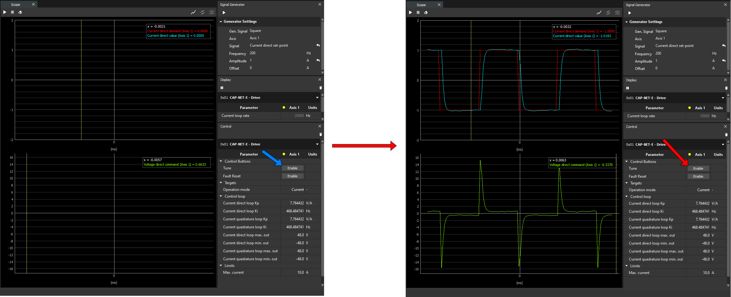
In order to make a tuning in this wizard, click on the Enable button of the Tune in the Control widget.
You notice both charts start to show some information:
Chart above shows the current direct, the actual value (blue) and the demand (red).
Chart below shows the voltage direct (green).
Notice the current demand is set in the Signal Generator widget.
In addition, you can see the dot next to “Axis 1” changes color:
Green color means the motor is enabled
Yellow means the motor is disabled but active
Red means the drive is in fault state
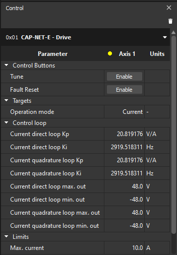
Control loop
On control widget you have 4 registers that you can change:
Current direct loop Kp.
Current direct loop Ki.
Current quadrature loop Kp.
Current quadrature loop Ki.
Both proportional parameters will be forced to have the same value, and the same with respect to quadrature parameters.
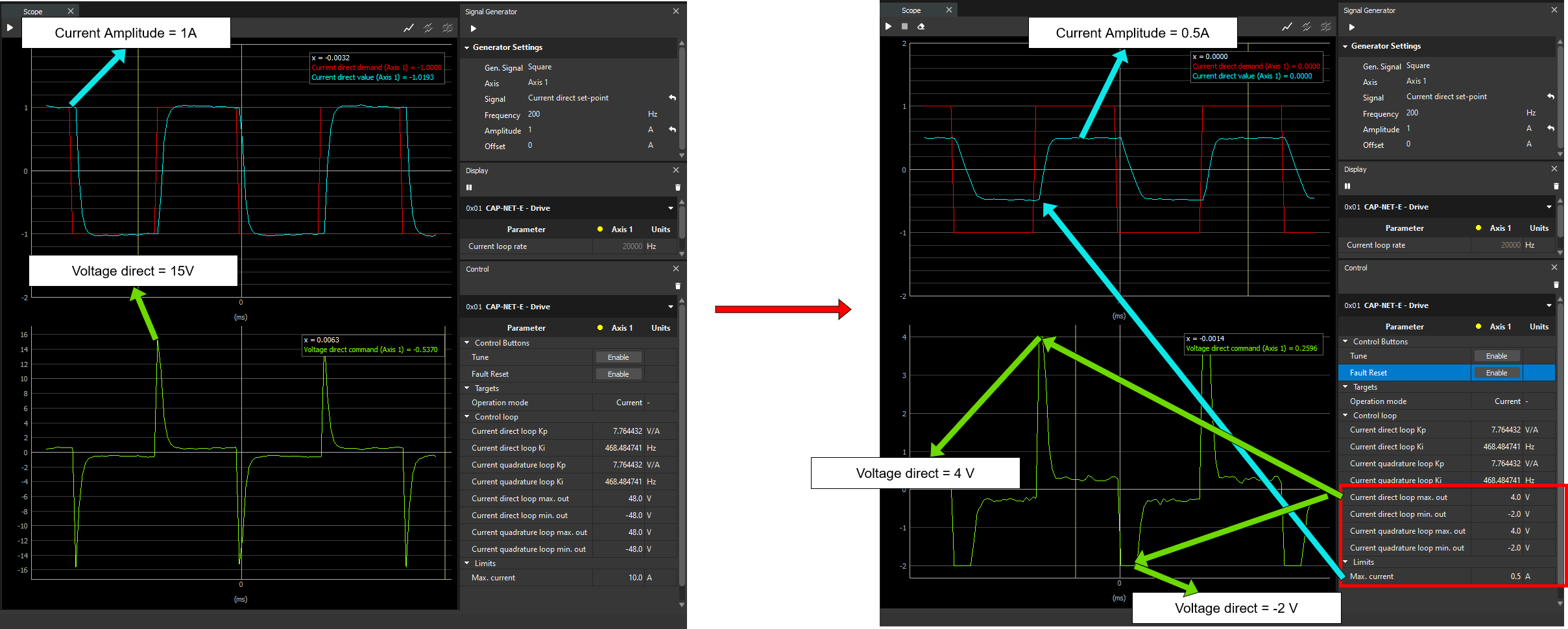
Limits
You can limit the maximum current loop amplitude as well as minimum and maximum voltage loop.
In the image below you can see an example about how these parameters can effect for your system (loop+plant)