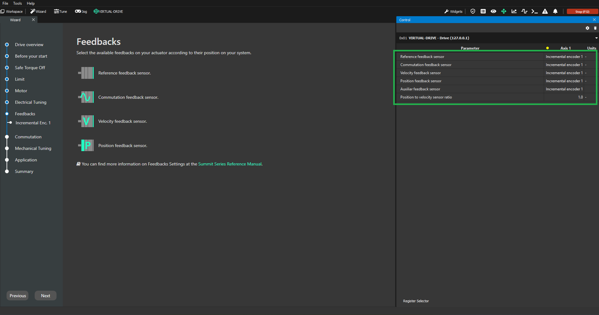
Feedbacks
This step is used to assign the correct functionality for each one of the feedback sensors that you have wired to your drive. This is done by setting the parameters accordingly in the Control widget (green square below). For each different sensor that is selected for commutation/reference/velocity/position purposes, an additional step will be added in the Wizard in order to configure that particular sensor properly. This step is also used to configure gearbox ratios.
It is important to make sure that a proper controller design has been done for the current direct/quadrature loops before attempting this step. This can either be done with the Electrical Tuning step or tuning the loops manually as well. It is also important to perform these feedback calibrations with the shaft of the motor without any load on it.
If you are interested in learning more about the parameters configured in this step, please refer to the firmware manual documentation: Feedbacks.
Parameters to configure
Reference feedback sensor → sensor used as the reference for commutation
Commutation feedback sensor → sensor used for commutation purposes
Velocity feedback sensor → sensor used for velocity control
Position feedback sensor → sensor used for position control
Auxiliar feedback sensor → sensor used as an auxiliar
Position to velocity sensor ratio → ratio between the sensor used for velocity control and the sensor used for position control
Feedback combinations (Everest XCR/NET/CORE)
Feedback sensor | Incremental encoder | Digital Halls | SSI | Secondary SSI | BiSS-C | BiSS-C (dual in daisy-chain) |
|---|---|---|---|---|---|---|
Incremental encoder | ||||||
Digital Halls |
| |||||
SSI |
|
| ||||
Secondary SSI |
|
| ||||
BiSS-C |
|
| ||||
BiSS-C (dual in daisy-chain) |
|
|
|
|
Example
A system composed of:
Motor with incremental encoder and hall sensors at the back of the motor
Gearbox with ratio of 1:50
SSI encoder on the output of the gearbox
Feedback assignment:
Commutation sensor (0x151 key) → Digital encoder 1 (value of 4)
Reference sensor (0x153 key) → Digital halls (value of 5)
Velocity feedback sensor (0x360 key) → Digital encoder 1 (value of 4) or Primary SSI (value of 1) encoder according to application preferences
Position feedback sensor (0x361 key) → Primary SSI (value of 1)
Position to velocity sensor ratio determination:
Case 1 (velocity feedback sensor is incremental encoder) → ratio = 0.02
Case 2 (velocity feedback sensor is SSI encoder) → Ratio = 1