Tune
Basic composition of tuning windows and how to use them
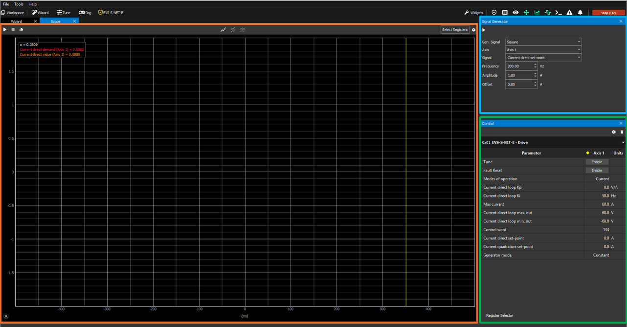
The Tune windows in MotionLab3 are workspaces designed to allow manual tuning and testing for the different modes of operation (current direct/quadrature, velocity, and position). These workspaces are composed of the following widgets:
Control (green box below) → widget used to modify the controller gains as well as additional parameters that can be useful during tuning operations.
Scope (orange box below) → widget used to plot the tuning response by comparing a signal generated from the drive with the response that the motor has for the specific loop (current, velocity or position).
Signal Generator (blue box below) → widget used to generate the demand/reference signal that the user will try to tune the controller gains around. In an ideal case, the tuned signal should be exactly the same as this signal generated from the drive.
Once you click the "Enable Tune" button, you will start seeing in real-time the response of the system for the current gains of the PI/PID controller of the loop.
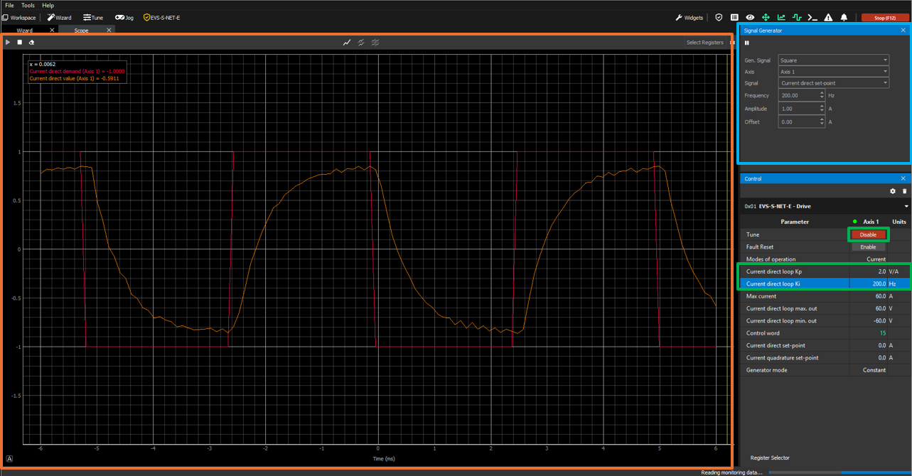
During this real-time representation of the response of the system, you can change the gains of the controller as you wish and see the updated response of the system for these new gains. This procedure is repeated until the performance of the PI/PID controller is acceptable and fulfils the needs of the user.

Current direct Tune window
If you want to get a deeper understanding of how this current direct loop is implemented inside the drive, please refer to the following documentation: Current modes (CSC, C, CA).
Parameters to tune
Kp → gain whose control action is proportional to the error between the current direct demand and actual values.
Ki → gain whose control action is proportional to the error between the current direct demand and actual values integrated over time.
Kr → gain that allows changing the controller architecture from an I+P (Kr = 0) controller to a PI (Kr = 1) controller. Intermediate values of Kr between 0 and 1 will provide a hybrid controller with both I+P and PI characteristics, weighted proportionally to the value of Kr.
Additional parameters
Current direct loop max. out → maximum voltage that will be applied to the phases of the motor. It acts as a saturator.
Current direct loop min. out → minimum (negative) voltage that will be applied to the phases of the motor. It acts as a saturator.
Max current → maximum current that will be applied to the phases of the motor.
Signal Generator
Gen. Signal → shape of the generated signal. Can be Square, Sinusoidal or Sawtooth.
Signal → signal that will be generated with the settings below. For this workspace, this is the current direct set-point.
Frequency → frequency of the generated signal in Hz.
Amplitude → amplitude of the demanded signal in A.
Offset → offset of the demanded signal in A.
Note: gains for current direct loops should be the same as gains for current quadrature loop.
Current quadrature Tune window
If you want to get a deeper understanding of how this current quadrature loop is implemented inside the drive, please refer to the following documentation: Current modes (CSC, C, CA).
Parameters to tune
Kp → gain whose control action is proportional to the error between the current quadrature demand and actual values.
Ki → gain whose control action is proportional to the error between the current quadrature demand and actual values integrated over time.
Kr → gain that allows changing the architecture of the controller from an I+P (Kr = 0) controller to a PI (Kr = 1) controller. Intermediate values of Kr between 0 and 1 will provide a hybrid controller with both I+P and PI characteristics, weighted proportionally to the value of Kr.
Additional parameters
Current quadrature loop max. out → maximum voltage that will be applied to the phases of the motor. It acts as a saturator.
Current quadrature loop min. out → minimum (negative) voltage that will be applied to the phases of the motor. It acts as a saturator.
Max current → maximum current that will be applied to the phases of the motor.
Signal Generator
Gen. Signal → shape of the generated signal. Can be Square, Sinusoidal or Sawtooth.
Signal → signal that will be generated with the settings below. For this workspace, this is the current quadrature set-point.
Frequency → frequency of the generated signal in Hz.
Amplitude → amplitude of the demanded signal in A.
Offset → offset of the demanded signal in A.
Velocity Tune window
If you want to get a deeper understanding of how this velocity loop is implemented inside the drive, please refer to the following documentation: Velocity modes (CSV, PV, V).
Parameters to tune
Kp → gain whose control action is proportional to the error between the velocity demand and actual values.
Ki → gain whose control action is proportional to the error between the velocity demand and velocity actual values integrated over time.
Kd → gain whose control action is proportional to the derivative of the error between the velocity demand and velocity actual values at a given instant of time.
Additional parameters
Velocity loop max. out → maximum current that will be input to the current quadrature loop. It acts as a saturator.
Velocity loop min. out → minimum (negative) current that will be input to the current quadrature loop. It acts as a saturator.
Max velocity → maximum velocity that the motor will be able to reach.
Signal Generator
Gen. Signal → shape of the generated signal. Can be Square, Sinusoidal or Sawtooth.
Signal → signal that will be generated with the settings below. For this workspace, this is the velocity set-point.
Frequency → frequency of the generated signal in Hz.
Amplitude → amplitude of the demanded signal in rev/s.
Offset → offset of the demanded signal in rev/s.
Position Tune window
If you want to get a deeper understanding of how this position loop is implemented inside the drive, please refer to the following documentation: Position modes (CSP, PP, IP, P).
Parameters to tune
Kp → gain whose control action is proportional to the error between the position demand and actual values.
Ki → gain whose control action is proportional to the error between the position demand and position actual values integrated over time.
Kd → gain whose control action is proportional to the derivative of the error between the position demand and position actual values at a given instant of time.
Additional parameters
Position loop max. out → maximum velocity that will be input to the velocity loop. It acts as a saturator.
Position loop min. out → minimum (negative) velocity that will be input to the velocity loop. It acts as a saturator.
Max position → maximum absolute position that will not be exceeded while the motor is enabled. It acts as a limit.
Min position → minimum absolute position that will not be exceeded while the motor is enabled. It acts as a limit.
Signal Generator
Gen. Signal → shape of the generated signal. Can be Square, Sinusoidal or Sawtooth.
Signal → signal that will be generated with the settings below. For this workspace, this is the position set-point.
Frequency → frequency of the generated signal in Hz.
Amplitude → amplitude of the demanded signal in cnt.
Offset → offset of the demanded signal in cnt.
Always remember that, if it makes your life easier, you can add additional variables to your workspace to improve the tuning process, and save the workspace configuration into a file. More on this here: Workspaces | How-to-save/load-workspaces