Incremental encoder
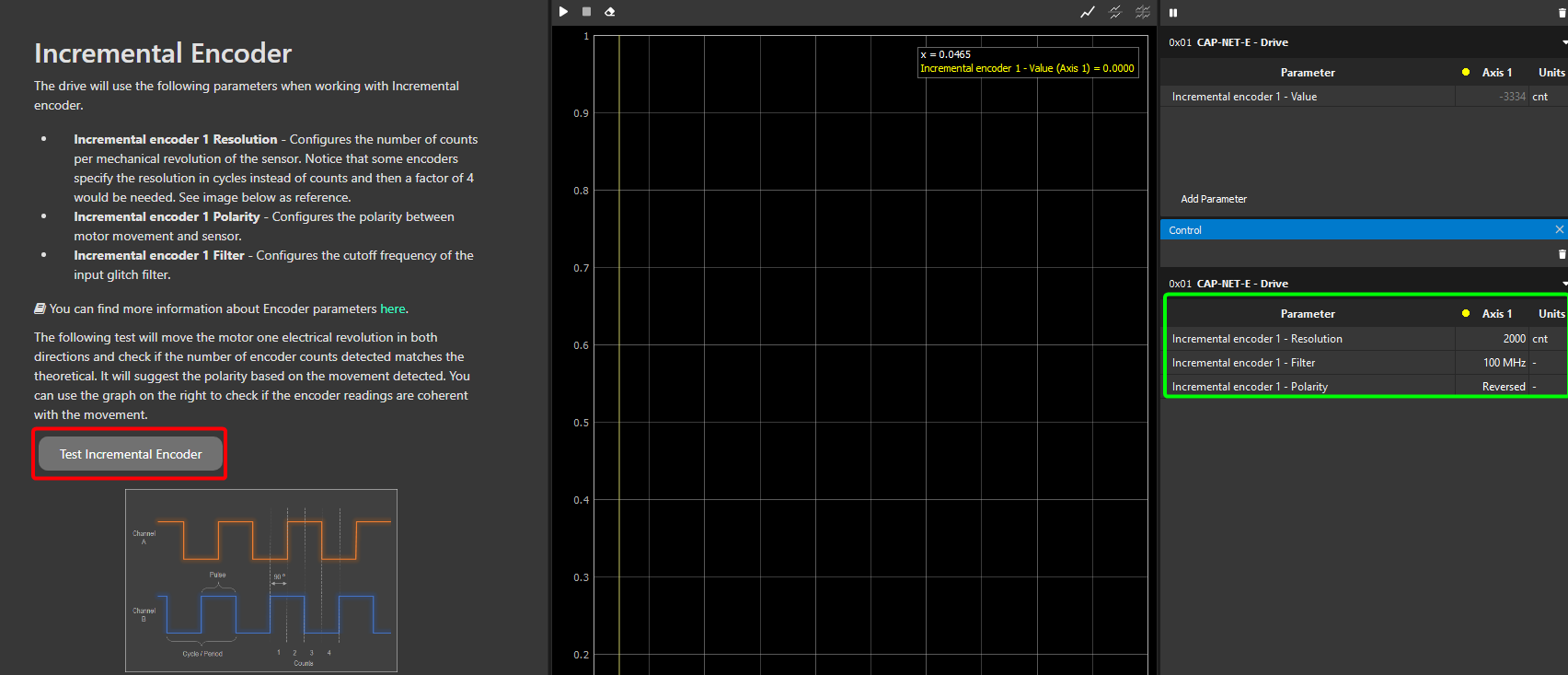
This step explains how to configure an incremental encoder properly in the configuration Wizard. In order to do it, you need to properly fill the parameters associated with this encoder in the Control widget (green square below). Then run the test (red)
Parameters to configure
Resolution → Resolution of the encoder in total counts per mechanical revolution. This is normally the pulses per revolution (ppr or lpr) value that you get from the datasheet multiplied x4.
Filter → Glitch filter levels of the digital encoder module. There are 10 different glitch filter levels. Each level corresponds to a specific cut-off frequency. Setting this parameter to 0 (100 MHz) will disable the glitch filter.
Polarity → The polarity of the feedback sensor is a parameter that relates how the position readings change when a positive voltage is applied to the phases of the motor. It can either be "Standard" or "Reversed".
Understanding how the polarity works
If with polarity set as "Standard, the position increases when a positive voltage is applied, then the polarity is correct as "Standard". On the other hand, if the position readings were to decrease, then the polarity setting would be wrong and you would need to change it to "Reversed" for this particular feedback sensor. Having a correct polarity setting is essential to having the sensor working properly and this is exactly what the incremental encoder test is meant to calculate. On an additional note, the polarity of the incremental encoder does not relate to the polarity of any other feedback sensor in the system (they can be the same or opposite, it does not matter).
If you are interested in learning more about the parameters configured in this step, please refer to the firmware manual documentation: Incremental encoder.
Incremental encoder test
This test has the following purposes:
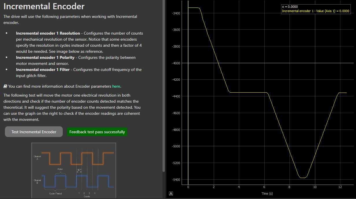
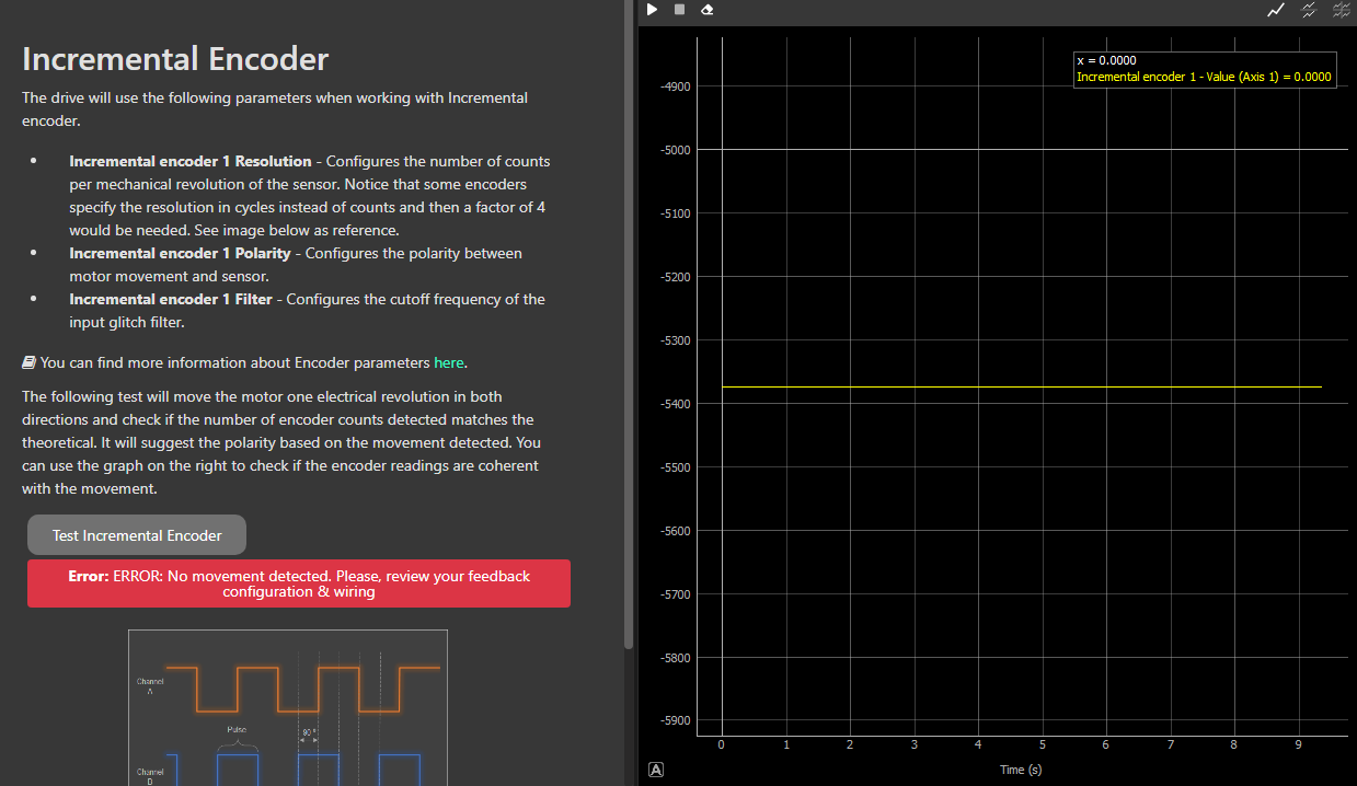
Validate that the resolution and pole pairs parameters introduced by the user are correct → This is done by moving a predefined range of motion and counting the position readings. If the readings match the expected values, the test is successful. If they do not match, the test fails, and you need to recheck both parameters to identify which one might be incorrect. A visual check of the movements can also help determine if the correct pole pairs parameter has been set. Check for the following motor movements: first, an alignment movement; second, a full revolution in one direction; and a final full revolution in the opposite direction.
Determine the polarity of the incremental encoder → This is done by applying always positive voltage first and then negative voltage and seeing how the position readings change. Please note that this polarity determination is not done if the previous validation does not turn out successfully.
Therefore, this test has only two possible outcomes:
Failed test
Success test