Velocity Temporal Design
Introduction
In previous step a tuning in a frequency domain was performed, in this wizard you are going to make it in time domain. You will see how the bandwidth affects your system (control loop+plant) in real time.
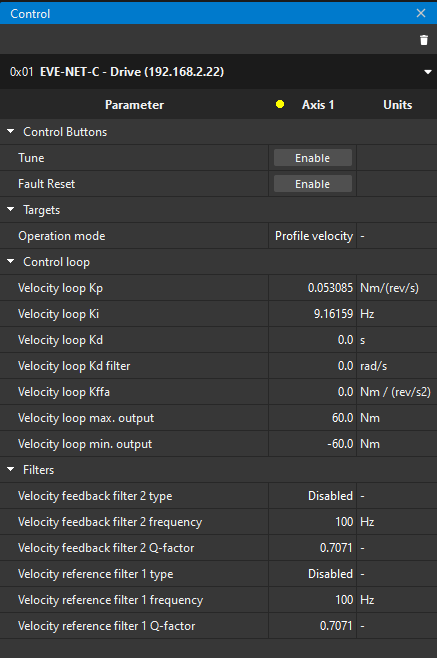
Control widget
This widget has several subparts for this wizard:
Buttons for Tuning and Fault Reset enabling.
Velocity control loop parameters
Filters
Further information about these registers, click on here.
Tuning
You can use this wizard to verify visually that the tuning is good.
In order to make a tuning in this wizard, click on the Enable button of the Tune in the Control widget.
You notice both charts start to show some information:
Chart above shows the actual velocity (blue) and the demand (red).
Chart below shows the current quadrature (green).
Notice the velocity set-point is set in the Signal Generator widget.
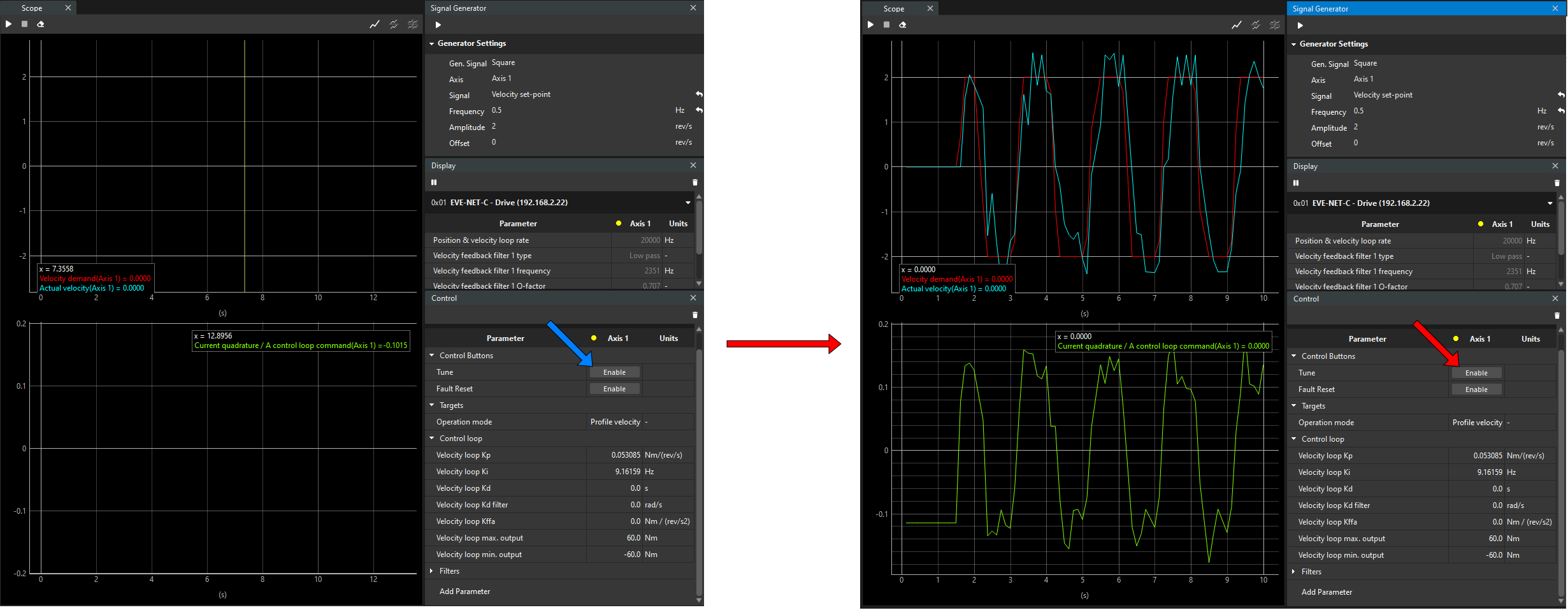
In addition, you can see the dot next to “Axis 1” is changed from yellow to green. Green color means the motor is enabled, yellow means the motor is disabled but active, and red means the drive is in fault state.