I/O connections
The Titan Go Servo Drive provides various inputs and output terminals for parameter observation and drive control options. These inputs can also be used for some feedback purposes (see Feedback connections).
The input and output pins are summarized below:
- 3 x 5 V general purpose isolated single ended digital inputs (GPI1, GPI2, GPI3).
- 2 x 5 V high-speed isolated single ended digital inputs (HS_GPI1, HS_GPI2).
- 1 x ±10 V isolated differential 12 bits analog input (AN_IN1).
- 1 x 3.3 V isolated digital output (GPO1).
Apart from the general purpose inputs, Titan Go has a dedicated analog input for measuring the motor temperature.
Wiring recommendations
Wiring recommendations for I/O signals are the same than for feedback signals. Detailed information about good wiring practices can be found in Feedback wiring recommendations.
Low-speed and High-speed single ended digital inputs interface (GPI1, GPI2, GPI3, HS_GPI1, HS_GPI2)
The general purpose isolated digital inputs are ready for 5 V levels. Next table show their electrical specifications.
Specification | Value |
|---|---|
Number of inputs | 5 (GPI1, GPI2, GPI3, HS_GPI1, HS_GPI2) |
Type of input | Isolated. Single ended. Low-pass filtered. ESD protected |
ESD capability | IEC 61000-4-2 (ESD) ± 15 kV (air), ± 8 kV (contact) |
Input current | 0.17 mA @ 5 V; 1 mA @ 15 V |
High level input voltage | 3 V < Vin < 5 V |
Low level input voltage | 0 < Vin < 1.2 V |
| Input impedance | 10 kΩ |
1st order filter cutting frequency (-3 dB) | 338 kHz |
| Sampling rate | 1 ksps |
Max delay | 2.3 μs |
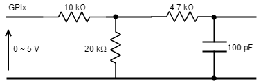
General purpose inputs electrical equivalent circuit is the following:
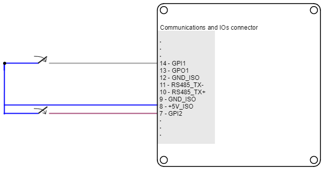
Next figure shows an example of how to connect a switch to the GPI1 and GPI2, using +5V_ISO (pin 8) pin as a supply source. Same connection could used for GPI3.
24 V inputs
To get 24 V inputs compatibility, just place a resistor of ≈ 80 kΩ in series with the input.
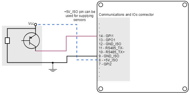
Titan Go Servo Drive general purpose inputs can be used for connecting three-wire sensors. Next figures illustrate the connection of PNP and NPN three-wire sensors in input GPI1 (same wiring can be used for GPI2, GPI3 and HS_GPI1 and HS_GPI2). Pin 8 (+5V_ISO) can be used as a supply source.
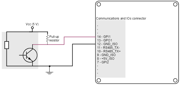
GPI Pull-up resistors
Pull-up resistors ensure the desired logic state when the sensor (transistor or relay) is in off-state.
NPN pull-up resistor value must be chosen in order to ensure ≥ 4 V at the GPI pin considering the 10 kΩ input resistance. For a sensor supply of 5 V, 1 kΩ is recommended.
Analog inputs interface (AN_IN1)
Titan Go Servo Drive has one 12-bit analog input (AN_IN1), which is differential. Next table summarizes the main features of the analog input:
Specification | Analog input 1 |
|---|---|
Type of inputs | Isolated. Differential. ESD protected |
| ESD capability | ± 8 kV (contact) |
Analog input resolution | 12 bits |
Maximum operating voltage | ±10 V |
| Maximum common mode voltage (Analog input 2) | ±10 V |
| Maximum voltage on any pin (referred to GND) | 10 V |
| 1st order filter cutting frequency (-3dB) | 116 kHz |
| Sampling rate (max) | 10 ksps |
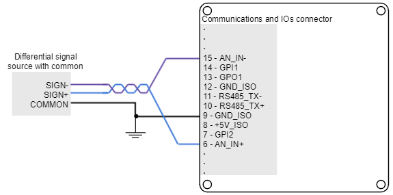
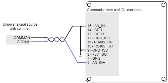
Next figure shows how to interface differential and single ended voltage sources to the differential analog input 1. The differential analog input is typically used as a command source or feedback signal.
Digital outputs interface (GPO1)
Titan Go Servo Drive has one digital isolated output. This digital output is intended for signalling, as it is the output of a digital isolator.
Specification | Value |
|---|---|
Number of outputs | 1 |
Type of output | Isolated. Logic digital output. ESD protected. |
Maximum supply output | 3.3 V |
Maximum sink/source current | Source: low current @ 3.3 V: 10 mA |
Max working frequency | 1 kHz |
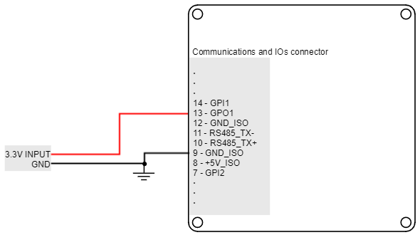
Wiring of 3.3 V loads
Loads that require 3.3 V as high-level voltage can be connected directly to the digital output. A wiring example for GPO1 is shown in the next figure.
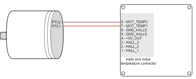
Motor temperature input (MOTOR_TEMP)
The Titan Go has a dedicated analog input for measuring the motor temperature, which can be found in the Halls and motor temperature connector. The motor temperature input is connected to the internal analog input 3 and allows the connection of an external temperature sensor (PTC thermistor, bimetal, NTC) to measure the motor temperature.
This analog input includes a 30 kΩ pull-up for directly connecting a NTC thermistor. Following is shown the circuit and an example of temperature sensor wiring:
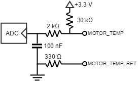
Suggested PTC
The suggested NTC thermistor value is a 100 kΩ nominal resistance (@ 25 ªC) as Vishay NTC (NTCALUG01A104F).
Main specifications of the external temperature sensor input are shown in the next table:
Specification | Value |
|---|---|
Type of input | Single ended analog |
| Mapping | Analog input 3 (AN_IN3) |
1st order low-pass filter cutting frequency (-3dB) | 800 Hz |