Feedback connections
The Titan Go Servo Drive has multiple connectors (Halls and motor temperature connector, Digital/Absolute encoder connector and Resolver connector) dedicated to the following feedback options:
Additional feedback connections can be found on Communications and IOs connector:
Titan also provides a 5 V, 50 mA output for Halls supply and a 5 V, 200 mA output for Encoders supply. These outputs are overload and short circuit protected.
Digital Halls interface
The Hall sensors are Hall effect devices that are built into the motor to detect the position of the rotor magnetic field. Usually, motors include 3 hall sensors, spaced 120º apart. Using these 3 signals, the drive is capable to detect the position, direction and velocity of the rotor. Next figures show examples of digital halls signals.
Digital halls signals example |
|---|
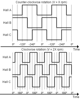 |
Digital halls can be used for commutation, position and velocity control. Resolution using these sensors is much lower than using encoders. Titan Go can use single ended Hall sensors to drive the motor with trapezoidal commutation, but not with sinusoidal commutation.
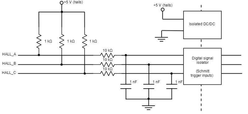
This interface accepts 0-5 V level input signals. Inputs are pulled up to 5 V, so industry standard open collector and logic output hall effect sensors can be connected. Next table summarizes digital halls inputs main features:
Specification | Value |
|---|---|
Type of inputs
| Isolated |
Number of inputs | 3 |
ESD capability | IEC 61000-4-2 (ESD) ± 15 kV (air), ± 8 kV (contact) |
Voltage range | 0 ~ 5 V |
| Maximum voltage range | -0.5 ~ 5.5 V |
| Maximum recommended working frequency | 1 kHz |
1st order filter cutting frequency (-3dB) | 16 kHz |
| Sampling frequency | 10 ksps |
Type of sensors | Open collector |
| Pull-up resistor value | 1 kΩ |

Next figure shows the circuit model of the digital Halls inputs.
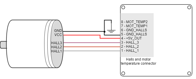
Next figure illustrates how to connect the digital halls to the Titan Go Servo Drive. Refer to Feedback wiring recommendations for more information about connections and wires.
Velocity control with Halls
Due to inherent low resolution of motor mounted Hall sensors, they are not recommended for velocity feedback in low speed applications.
Digital Incremental Encoder
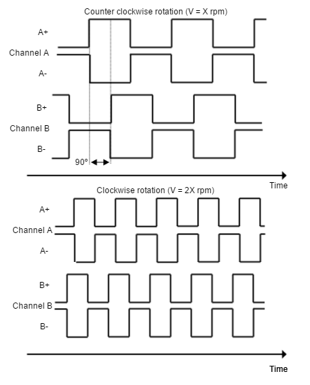
Titan Go can use differential digital incremental encoder inputs (also known as quadrature incremental encoders) for velocity and/or position control, as well as commutation sensor. The encoder provides incremental position feedback that can be extrapolated into precise velocity or position information. Using high resolution encoders allows Titan Go Servo Drive to use sinusoidal commutation.
Channel A and channel B signals should have a phase shift of 90 degrees, indicating the rotation direction. Based on the pulses frequency, the drive can calculate the motor velocity and position.
| Example of digital differential encoder signals |
|---|
|
High precision applications
High resolution motor mounted encoders allows excellent velocity and position control at all speeds. Encoder feedback should be used for applications requiring precise and accurate velocity and position control. Digital encoders are especially useful in applications where low-speed smoothness is the objective.
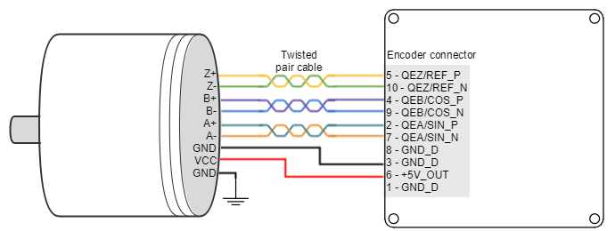
The Titan Go Servo Drive has one differential digital encoder interface, with optional index signal input. Index (Z) is a single pulse per revolution signal that indicates an absolute position. Next table lists digital encoder inputs main features.
Specification | Value |
|---|---|
Type of inputs | Non-isolated. Differential. ESD protected |
Number of inputs | 3 (A, B and Index) |
ESD capability | IEC 61000-4-2 (ESD) ± 15 kV (air), ± 8 kV (contact) |
Nominal voltage range | 0 ~ 5 V |
Maximum voltage range | -15 ~ 15 V |
| Maximum recommended working frequency | 10 MHz (differential) |
1st order filter cutting frequency (-3 dB) | 6 MHz |
| Maximum readable pulse frequency | 30 MHz |
| Termination resistor | 470 Ω (between ENC_x+ and ENC_x-) |
| Bias resistors | ENC_x- (negative input) 1 kΩ to 3.3 V (equivalent) |
The encoder interface accepts an RS-422 differential quadrature line driver signal in the range of 0 V to 5 V, up to 10 MHz.
Next figures illustrate how to connect a differential and a encoder to the Titan Go Servo Drive. Refer to Feedback wiring recommendations for more information about connections and wires.
Absolute encoder interface
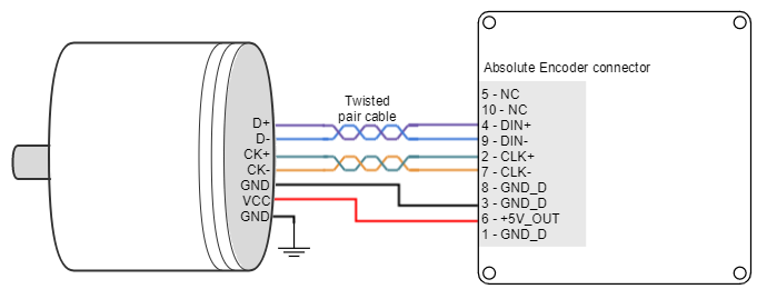
The Titan Go has an Absolute encoder connector that can be used as position and velocity feedback element. This sensor generates digital data that represent the encoder actual position. From the position information, speed and direction of motion is calculated. The position is not lost even if the encoder is powered down, this means it is not necessary to move to a reference position as with incremental type encoders.
Next table shows the absolute encoder inputs electrical specifications.
Specification | Value |
|---|---|
Type of inputs | Non-isolated. Differential. ESD protected |
ESD capability | IEC 61000-4-2 (ESD) ± 15 kV (air), ± 8 kV (contact) |
| Number of inputs | 2 (CLK and DATA_IN) |
| Nominal voltage range | 0 ~ 5 V |
| Maximum voltage range | -15 ~ 15 V |
| Maximum readable frequency | 1 kHz |
| Termination | 470 Ω |
Next Figure shows how to connect an Absolute encoder to Titan Go Servo Drive. Refer to Feedback wiring recommendations for more information about connections and wires.
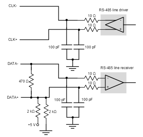
Circuit model for the absolute encoder receiver channels is shown in the next figure.
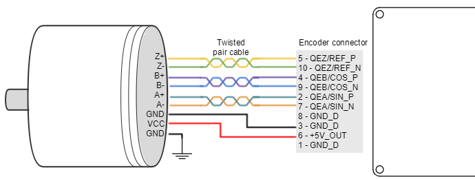
Analog encoder (Sin-Cos encoder) interface
The Titan Go can use analog encoder (also known as Sin-Cos encoder) as position and velocity feedback element. This sensor provide a pair of quadrature sine and cosine signals as the motor moves, which frequency depends on the motor speed. The signals may be generated by optical or magnetic means. For noise immunity the signals are typically transmitted differentially from the encoder to the sensor interface electronics.
| Pin | Signal description | Signal example |
|---|---|---|
SIN+ | Sine wave with 2.5 V offset and 0.5 Vpp | 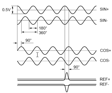 |
| SIN- | Same as SIN+, but with 180º phase shift | |
| COS+ | Cosine with 2.5 V offset and 0.5 Vpp | |
| COS- | Same as COS+, but with 180º phase shift | |
| REF+ | One sine half wave per revolution as index pulse | |
| REF- | Same as REF+, but with 180º phase shift |
Sin-Cos calibration
Analog encoder signals are not always perfect sine and cosines. For this reason, Titan includes sin-cos calibration and adjustment parameters. For further information see the E-Core registers for Sin-Cos encoder configuration.
An automatic calibration based on Lissajous curves is included in MotionLab, which allows an easy feedback adjustment.
Next table summarizes analog encoder inputs main features.
Specification | Value |
|---|---|
Type of inputs | Differential analog input (switching to digital automatically at high speed) |
Number of inputs | 3 (SIN, COS, REF) |
ESD capability | IEC 61000-4-2 (ESD) ± 15 kV (air), ± 8 kV (contact) |
| Typical voltage range | 2.25 ~ 2.75 V |
| Maximum voltage range | -0.5 ~ 5.5 V |
Maximum recommended working frequency | 1 kHz used as analog encoder 10 MHz used as digital encoder |
1st order filter cutting frequency (-3 dB) | 6.6 MHz |
| Sampling rate (analog) | 10 ksps |
| Maximum readable pulse frequency (digital) | 30 MHz |
Input impedance | 120 Ω resistive differential 100 pF capacitive 1 kΩ to GND |
Resolution | 10 bits |
Next figure shows how to connect a Sin-Cos encoder to Titan Go. Refer to Feedback wiring recommendations for more information about connections and wires.
Circuit model for each differential channel (A, B, REF) is shown in the next figure.
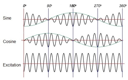
Resolver interface
The Titan Go has a Resolver connector that can be used as position and velocity feedback element, as well as commutation sensor. A resolver is an electromagnetic transducer that can be used in a wide variety of applications. Because of its simple transformer design and lack of any on board electronics, the resolver is a much more rugged device than most any other feedbacks, specially in extreme conditions (high temperature, shock and vibration, radiation and contamination). The resolver needs an excitation signal generated by the drive, which is modulated in proportion of the sine and cosine of the angle of mechanical rotation. The sine and cosine signals are read by the drive and processed by the drive to know the rotor position. Next figure show an example of digital resolver signals.
| Example of resolver signals |
|---|
|
Next table shows the resolver electrical specifications.
Specification | Value |
|---|---|
Type of inputs | Non-isolated. Differential. ESD protected |
ESD capability | IEC 61000-4-2 (ESD) ± 15 kV (air), ± 8 kV (contact) |
| Number of inputs | 2 (SIN and COS) |
| Number of outputs | 1 (EXC) |
| Excitation signal voltage | 10.8 Vpp (7.6 VAC) * |
| Excitation frequency | 10 kHz * |
| Transform ratio | 1:0.5 * |
*These values can be adjusted to the customer needs on demand. Please, notify the desired resolver specifications when ordering a Titan Go.
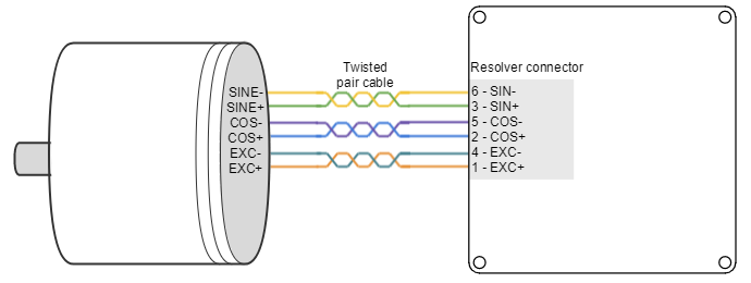
The following picture shows how to connect the resolver to the Titan Go servo Drive:
Resolver Gain
Titan default setting is for a resolver with a transform ratio of 1:0.5. The transform ratio can be adjusted at Ingenia facilities. Please notify the desired resolver specifications when ordering a Titan.
The SIN and COS inputs expect a differential voltage (between positive and negative terminals) of 1.4 VRMS or 3.9 Vpk-pk. However, in some cases it is possible to adjust the gain by adding a resistor in series with the SIN and COS inputs. This will make a voltage divider with the input differential resistance of 26 kΩ. When the gain is correct, the LOT and DOS LEDs are off.
Configuring the resolver
Resolvers with independent rotor and stator require fine positioning. Ensure perfect collinearity between them and follow the resolver manufacturer instructions.
Both resolver LEDs (LOT and DOS) OFF indicate that the resolver is well positioned and wired.
- Configure that resolver is the position and or commutation sensor of the driver. Use Ingenia Motion Lab software for the configuration. Use CANopen or USB for the purpose.
- With motor disabled check the motor position read by the resolver. Rotate the motor and ensure that position is well read. Use Ingenia Motion Lab scope with position actual value register being monitored.
- If some of the orange or blue LEDs are on this means incorrect resolver gain or alignment. Check the correct relative position between stator and rotor of the resolver. Use an oscilloscope to detect the amplitude of sine and cosine (differential) and ensure a sine wave with desired amplitude is observed (peak 3.9Vp-p of sine and cosine at their maximum). Too much amplitude or too low causes a degradation of read signal
Trick: The gain can be changed by sliding the resolver rotor inwards or outwards relative to the stator. (Z axis). This changes the reluctance and affects the transform ratio. - Enable the motor in open loop vector mode, no current loop, no position or velocity loop. Set frequency to 1 Hz or lower and start increasing the voltage gently. Use the motion window in motion lab. Observe that the motor starts moving. Read motor actual current with the scope.
- Check that the resolver position is well read. If reading errors appear only when the motor is on, this could mean some noise being coupled to the resolver and degrading the signal. Wire the resolver as far as possible from the power cables (to prevent noise coupling). Ensure a good thick and short cable connects the motor housing and the driver PE (Earth) contact. Connecting the motor housing to PE creates a short impedance path for coupled noise and therefore is not coupled to the resolver.
- If the installation allows this connect the motor housing to the main supply negative (GND). Only do so if an experienced electrician with perfect understanding of the installation and system knows that this is correct.
- When no error appear with motor turning and active (orange and blue leds always off). You can proceed and configure commutation sensor. After that configure the control loops, starting with the current loop.
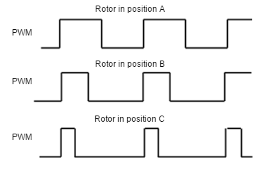
Digital input feedback - PWM encoder
Titan Go Servo Drive can also use a PWM encoder connected through the Communications and IOs connector as a feedback element. A PWM encoder provides a Pulse Width Modulated (PWM) signal with a duty cycle proportional to the angle (position) of the rotor. This feedback can be interfaced through the high-speed digital input 1 (HS_GPI1). Only single ended encoders can be used. Further specifications about the PWM input can be found in I/O connection section.
Next figure illustrates PWM feedback input for different rotor positions:
Next figures illustrates how to connect differential and single ended PWM encoders to the Titan Go Servo Drive:
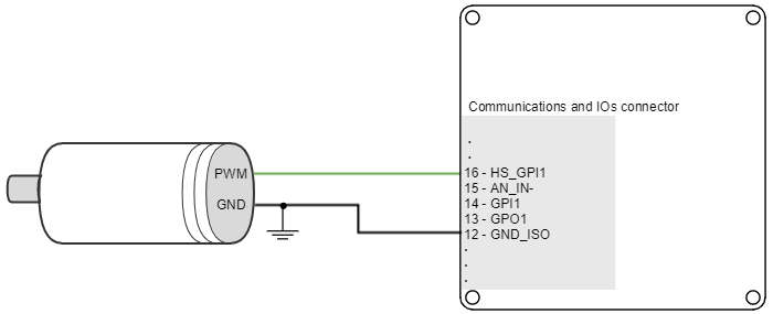
Refer to Feedback wiring recommendations for more information about connections and wires.
Analog input feedback
Titan Go Servo Drive can also use analog feedback systems connected through the Communications and IOs connector. From the voltage level of one analog input, the position or velocity of the rotor can be calculated. The Titan Go have 1 differential analog input that can be used for feedback input, with a range of ±10 V. The input used as feedback can be selected by software.
Refer to Feedback wiring recommendations for more information about connections and wires.
Potentiometer
Typically, a potentiometer is used as a postition feedback, providing a a voltage proportional to the rotor position.
The following picture shows how to connect a potentiometer as a position sensor using analog input 1:
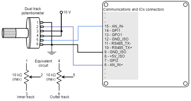
Recommended potentiometer resistance
Potentiometers with high values of resistance (> 10 kΩ) can result in non linear behavior due to its the drive parallel input resistors. High resistance values also reduce the signal to noise ratio, making it easier to have disturbances and reducing the quality of the measure.
However, a very small value of resistance may also consume too much power and cause self heating (which causes additional variations on resistance). Therefore, use the smallest value of resistance that:
- Does not exceed 1/2 of the potentiometer power rating (safety margin to prevent self heating).
- Does not exceed the +5V_OUT current capacity.
Typically 1 kΩ to 10 kΩ will be preferred.
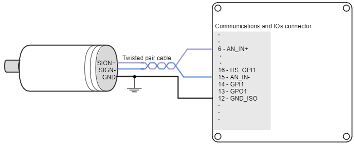
DC tachometer
The Titan Go Servo Drive can use a DC tachometer for velocity feedback through the Communications and IOs connector. A DC tachometer provides an analog signal whose voltage level is proportional to the rotor speed.
Next figure illustrates how to connect a DC tachometer with differential output to the Titan Go Servo Drive.
Feedback wiring recommendations
Signal distortion and electrical noise is a common problem in feedback signals. These problems can result in a bad position or velocity calculation for both digital feedbacks (gain or loss of counts) and analog feedbacks (wrong voltage levels).To minimize these problems some wiring recommendations are shown:
- Use differential signals whenever is possible. That is, connect both positive and negative signals of differential feedback sensors. Use a twisted pair for each differential group of signals and another twisted pair for the +5 V supply and GND. Twisted-pairs help in elimination of noise because disturbances induced in twisted pairs
- Twisted-pairs help in elimination of noise due to electromagnetic fields by twisting the two signal leads at regular intervals. Any induced disturbance in the wire will have the same magnitude and result in error cancellation.
- Connect the Titan Go and encoder GND signals even if the encoder supply is not provided by the drive.
- Connection between Titan Go PE and the motor metallic housing is essential to provide a low impedance path and minimize noise coupling to the feedback. For further information, see Protective Earth wiring.
- For better noise immunity, use shielded cables, with the shield connected to PE only in the drive side. Never use the shield as a conductor carrying a signal, for example as a ground line.
- It is essential to keep feedback wiring as far as possible from motor, AC power and all other power wiring.
Recommendations for applications witch close feedback and motor lines
In some applications, like in the subsea market, where additional connectors and cables are a problem, the feedback cannot be wired separately from the motor and power lines. This creates noise problems that could result in hall sensors wrong commutation errors or encoder loss of counts. For these applications we recommend:
- Use a common mode choke on the motor phases. This single action can reduce common mode noise drastically and will solve most problems. See recommended wiring in Motor and shunt braking resistor wiring.
- Ensure the motor housing is well connected to protective earth and the system chassis (PE).
- If possible, minimize power supply voltage. This will also minimize the electromagnetic noise generated by the motor switching.
- Add additional RC low pass filters on the feedback inputs. The filter should attenuate at a frequency above the maximum speed signal to prevent loss of counts and signal distortion. Preferably use resistors with low values to prevent distortion to the servo drive input circuit at low frequency (< 500 Ω). Use ceramic capacitors with good quality dielectric, like C0G.
For further information contact Ingenia engineers for support.