Denali Safe EVAL - Product Description
Denali Safe EVAL is a mid-power, highly integrated, ready-to-use digital servo drive. The drive includes all the required interface electronics and connectors and can be easily configured with free software MotionLab 3.
Denali Safe EVAL is designated as an evaluation product and is strictly for evaluation purposes for the Denali Safe NET drive. It is not approved for final application or production use.
Denali Safe EVAL is enabled with EtherCAT communications.
Main features:
Ultra-small footprint
Functional Safety: STO, SS1, SS2, SOS, SLS, SLP, SDI, SSR, SV, SP, FSoE; SIL3 and PLe being certified
48 VDC, 5 A continuous
Up to 99% efficiency
Up to 50 kHz current loop, 25 kHz servo loops
20 kHz ~ 200 kHz PWM frequency
16 bit ADC current sensing
Supports Digital Halls, Quadrature Incremental encoder, Absolute BiSS-C encoder
Up to 4 simultaneous feedback sources
Full voltage, current, and temperature protections
Capable of controlling low inductance motors
Part Numbering
Product | Ordering part number | Status | Image |
|---|---|---|---|
Denali EVAL | DEN-S-EVAL-E | PRODUCTION | 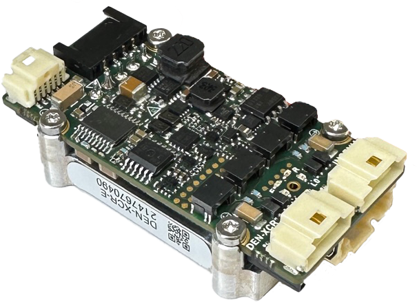 |
General Label Identification |
|---|
 |
Specifications
Electrical and Power Specifications
Minimum absolute power supply voltage | 8 VDC |
|---|---|
Maximum absolute power supply voltage | 60 VDC |
Recommended power supply voltage | 8 VDC ~ 48 VDC This voltage range ensures a safety margin including power supply tolerances and regulation during acceleration and braking. |
Internal drive DC bus capacitance | 19.7 µF Note that DEN-XCR uses ceramic capacitors. The capacitance value varies with DC bias and temperature. |
Boot-up time | 4 s |
Minimum shutdown time | 500 ms |
Maximum continuous phase current | 5 A 5 A can be obtained working at 48 V with an appropriate dissipation to keep the product plate under 85 ºC. On higher temperatures an automatic current derating will be applied to protect the system. See Thermal and Power Specifications below and Installation for further details. For disambiguation on current definitions please see Disambiguation on current values and naming for Ingenia Drives. |
Maximum peak phase current | 10 A @ 1 sec Notice that peak current could be limited by an automatic current derating algorithm. |
Maximum continuous output power | > 250 W How the output power is calculated. |
Motion Control Specifications
Supported motor types | Rotary brushless (SVPWM and Trapezoidal) |
|---|---|
Power stage PWM frequency (configurable) | 20 kHz, 50 kHz (default), 100 kHz, 200 kHz |
Current sensing | 3 phase, shunt-based current sensing. 16 bit ADC resolution. Accuracy is ±2% full scale. |
Current sense resolution | 0.505 mA/counts |
Current sense range | ± 16.5 Apk (full range) |
Maximum Current loop frequency | 50 kHz Check the Power Stage & Control loops relationship section below. |
Maximum servo loops frequency (position, velocity & commutation) | 25 kHz Check the Power Stage & Control loops relationship section below. |
Feedbacks |
All feedback inputs are single-ended, 3.3 V logic levels. The following feedback protocols are supported and can be used outside of the Functional Safety certification:
|
Supported target sources | Network communication: EtherCAT with Safety over EtherCAT (FSoE) |
EtherCAT |
|
Control modes |
|
Functional Safety Specifications
Denali Safe EVAL is designated as an evaluation product and is strictly for evaluation purposes for the Denali Safe NET drive. It is not approved for final application or production use.
The section below shows the Function Safety Specifications of Denali Safe NET.
DEN-S-NET-E Safe Motion | |
|---|---|
Safety functions |
|
Safe Feedback | Safe Feedback with the combination of 2 individual encoders:
See the supported Safe Feedback Combinations from below for further details. Safe Encoder are not being supported. |
Safety Integrity Level (SIL) according to IEC 61508:2010 | SIL3 |
Performance Level (PL) according to ISO 13849-1:2015 | PLe, Cat. 3 |
Safety Function Reaction Time | ≤ 25 ms |
Safe inputs | 1 x Redundant Safe Input. Non-Isolated. Logic level (3.3 V and 5 V tolerant). Active-low. |
Command Source |
|
FSoE cycle time | ≤ 50 ms |
Standards compliance |
|
Safe Feedback Combinations (DEN-NET-E Safe Motion - future release)
Denali Safe EVAL is designated as an evaluation product and is strictly for evaluation purposes for the Denali Safe NET drive. It is not approved for final application or production use.
The section below is relevant to the future implementation of the Denali Safe NET drive offering Safe Motion features.
Denali Safe NET can provide advanced Safe Motion functions by using two individual non-certified encoders:
Feedback Combination | ||
|---|---|---|
Combination code → MotionLab selection | Main feedback sensor | Redundant feedback sensor |
FBC0 → No feedback | - | - |
FBC1 → Primary absolute and secondary absolute | BISS-C BP3 - Port 1 | BISS-C BP3 - Port 2 |
FBC2 → Primary absolute and incremental encoder | BISS-C BP3 - Port 1 | QEI |
FBC3 → Secondary absolute and halls | BISS-C BP3 - Port 2 | Digital Halls |
FBC4 → Incremental encoder and halls | QEI | Digital Halls |
When no feedback sensors are used (FBC0), the available safety functions allowed represent STO, SS1 (time monitoring only) and SI.
In the case of using one of the above specified safety feedback combination the allowed safety functions are: STO, SS1, SI, SLS, SSR, SDI, SV, SS2, SS2, SOS, SLP, SLI and SP. For more information about the safety functions check the Safety Manual and the Reference manual.
Note: To guarantee enough diversity, the encoders must be of different technology or manufacturer.
Note: Other feedback combinations can be used for Motion Control purposes out of Functional Safety certification.
Note: Safe Encoders are not supported.
Inputs/Outputs and Protections
General purpose inputs and outputs | 2x non-isolated single-ended digital inputs - 3.3 V logic level & 5 V compatible. Can be configured as:
2x non-isolated single-ended digital outputs - 3.3 V logic level, short-circuit protected. Can be configured as:
2x ±11 V ,16-bit, differential analog inputs for load cells or torque sensors. Can be read by the Master to close a torque loop. 1x 0.3 V - 3 V buffered analog output:
|
|---|---|
Shunt braking resistor output | Configurable over any of the general purpose digital outputs (see above). Enabling this function requires an external transistor or power driver. |
Safe Inputs |
|
Motor temperature input | 1x dedicated, 3.3 V, 12-bit, single-ended analog input for motor temperature (1.65 kΩ pull-up to 3.3 V included). NTC, PTC, RTD, linear voltage sensors , silicon-based sensors and thermal switches are supported. |
Protections |
|
Compliance
Note: DEN-S-EVAL is an assembly of the DEN-S-NET, and a communication board. Compliance data for the DEN-S-NET can be found below.
EC Directives | CE Marking
|
|---|---|
Electromagnetic Compatibility (EMC) Standards |
|
Product Safety Standard |
|
Environmental Test methods | IEC 60068-2:
|
Power Stage & Control loops relationship
The power stage PWM frequency can be adjusted in 4 different frequencies. Each frequency has an associated rate for the control loops, as specified in the following table.
Power stage PWM frequency | Current loop frequency | Servo loops frequency (position, velocity, commutation & shunt) |
|---|---|---|
20 kHz | 20 kHz | 20 kHz |
50 kHz | 50 kHz | 25 kHz |
100 kHz | 50 kHz | 25 kHz |
200 kHz | 50 kHz | 25 kHz |