Switch on the power supply
Power supply
Ensure the supply will be capable of providing the power to move the motor: some low current power supplies can overload when enabling the motor (and turn-off) which causes the drive to reset.
STO
Ensure that the Safe Torque Off (STO) circuit is connected and powered as indicated in the manual. Otherwise, it will just not be possible to enable the motor.
Switch on the power supply and wait 10-15 seconds.
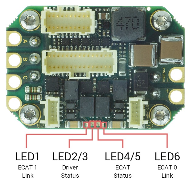
The drive provides information through 6 signalling LEDs:
| LED | Type | Color | Description |
|---|---|---|---|
| LED6 | Single | Green | EtherCAT / Ethernet 0 link (ECAT 0 Link or LINK0) |
| LED1 | Single | Green | EtherCAT / Ethernet 1 link (ECAT 1 Link or LINK1) |
| LED2/3 | Bi-color | Green / Red | Driver Status. Two LEDs indicate the driver status.
|
| LED4/5 | Bi-color | Green / Red | EtherCAT / CANopen Status (ECAT Status). Two LEDs indicate the EtherCAT or CANopen status.
|
The meaning of the signaling depends on the product variant, see LED signals reference for details.
LEDs at start-up & Troubleshooting
After powering on, some of the LED signals can help troubleshoot.
EtherCAT
Typical behaviour
If EtherCAT cables are connected on Port 0/1, Link LEDs will light according to the definition.
EtherCAT firmware will start with no other LED because the slave will stay in INIT State after power-up until an EtherCAT master forces it to transition to another state.
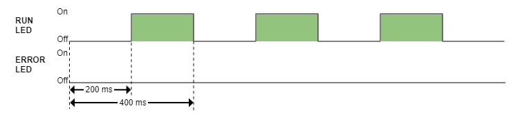
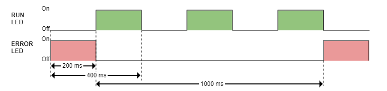
| LED signal | Start-up behaviour |
|---|---|
| RUN LED (Green) |
|
| ERROR LED (Red) |
|
| RUN & ERROR LED |
|
| FAULT LED (Red) |
|
The rest of the LED signals follow the standard behavior.
CANopen
| LED signal | Start-up behavior |
|---|---|
| RUN LED (Green) |
|
| ERROR LED (Red) |
|
| RUN & ERROR LED |
|
| FAULT LED (Red) |
|
The rest of the LED signals follow the standard behaviour