I/O connections
The Jupiter Servo Drive provides various inputs and output terminals for parameter observation and drive control options. These inputs can also be used for some feedback purposes (see Feedback connections).
The input and output pins are summarized below:
- 2 x 5 V general purpose non-isolated single ended digital inputs (GPI1, GPI2).
- 2 x 5 V high-speed non-isolated differential digital inputs (HS_GPI1, HS_GPI2).
- 1 x 0 ~ 5 V single ended 12 bits analog input (AN_IN1).
- 1 x ±10 V differential 12 bits analog input (AN_IN2).
- 2 x 5 V non-isolated digital outputs (GPO1, GPO2).
Wiring recommendations
Wiring recommendations for I/O signals are the same than for feedback signals. Detailed information about good wiring practices can be found in Feedback wiring recommendations.
General purpose single ended digital inputs interface (GPI1, GPI2)
The general purpose non-isolated digital inputs are ready for 5 V levels, but are 24 V tolerant. Next table show their electrical specifications.
Specification | Value |
|---|---|
Number of inputs | 2 (GPI1, GPI2) |
Type of input | Single ended |
ESD capability | IEC 61000-4-2 (ESD) ± 15 kV (air), ± 8 kV (contact) |
Input current | 0.7 mA @ 5 V; 2 mA @ 15 V |
High level input voltage | 4 V < Vin < 24 V |
Low level input voltage | 0 < Vin < 1 V |
| Input impedance | 30 kΩ |
1st order filter cutting frequency (-3 dB) | 100 kHz |
| Sampling rate | 1 ksps |
Max delay | 2 μs |
General purpose inputs electrical equivalent circuit is the following:
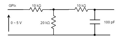
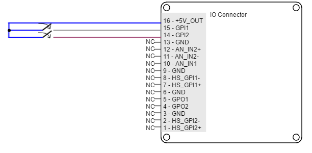
Next figure shows an example of how to connect a switch to the GPI, using +5V_OUT (pin 16) pin as a supply source.
Non-isolated I/O
Jupiter inputs and outputs are not isolated. The ground of the Jupiter Servo Drive and the ground of the devices connected to I/Os must be the same. Otherwise inputs or outputs may be damaged.
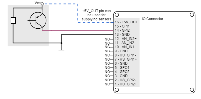
Jupiter Servo Drive general purpose inputs can be used for connecting three-wire sensors. Next figures illustrate the connection of PNP and NPN three-wire sensors in input GPI2 (same wiring can be used for GPI1). Pin 16 (+5V_OUT) can be used as a supply source.
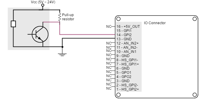
GPI Pull-up resistors
Pull-up resistors ensure the desired logic state when the sensor (transistor or relay) is in off-state.
NPN pull-up resistor value must be chosen in order to ensure ≥ 4 V at the GPI pin considering the 30 kΩ input resistance. For a sensor supply of 5 V, 1 kΩ is recommended. For a sensor supply of 24 V, 10 kΩ is recommended.
High-speed digital inputs interface (HS_GPI1, HS_GPI2)
The high-speed (HS) non-isolated digital inputs are ready for 5 V levels but are 24 V tolerant. Next table show their electrical specifications.
Defect logic value
Jupiter high-speed inputs are default low-level (OFF). When no signal or load connected, the board will detect a logic low.
Specification | Value |
|---|---|
Number of inputs | 2 (HS_GPI1, HS_GPI2) |
Type of input | ESD protected |
ESD capability | IEC 61000-4-2 (ESD) ± 15 kV (air), ± 8 kV (contact) |
Input current | 2 mA @ 5 V; 5 mA @ 15V |
High level input voltage | (HS_GPI+ - HS_GPI-) > 150 mV |
Low level input voltage | (HS_GPI+ - HS_GPI-) < -600 mV |
| Maximum working input voltage | ±24 V |
| Maximum recommended frequency | 10 MHz |
| Sampling rate | 20 Msps |
Total rising delay | 65 ns |
Total falling delay | 55 ns |
| Maximum common mode voltage (VCM) | -7 V ≤ VCM ≤ 12 V (VCM common mode input voltage) |
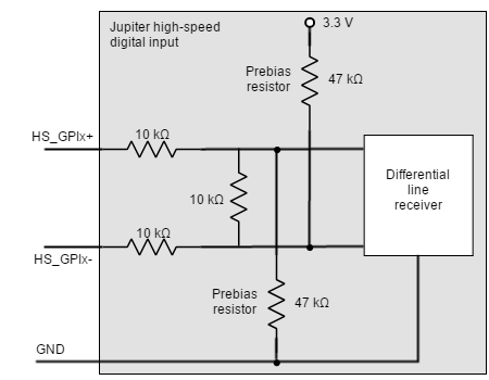
Next figure shows the circuit model for high-speed digital input. Input is composed of a 3-resistor differential divider, with 10 kΩ resistors, resulting in a total input impedance of 30 kΩ. This bias resistors allow both single ended and differential input operation. Noise immunity can be improved by reducing input impedance with a termination resistor between HS_GPI+ and HS_GPI-.
High-speed digital inputs electrical equivalent circuit is the following:
Non-isolated I/O
Jupiter Inputs and outputs are not isolated. The ground of the Jupiter Servo Drive and the ground of the devices connected to I/Os must be the same. Otherwise inputs or outputs may be damaged.
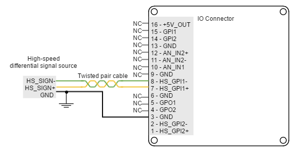
Next figure illustrates how to connect high-speed differential signal to HS_GPI1 (same wiring can be used for HS_GPI2).
Single ended operation
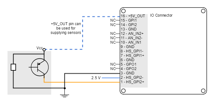
In order to use the high-speed digital input in single ended mode, connect the negative terminal (HS_GPIx-) to 2.5 V. This voltage can be achieved with a voltage divider from +5V_OUT.
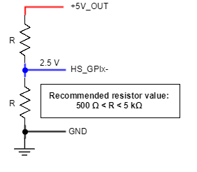
For a 24 V input, the negative terminal (HS_GPIx-) can be connected to 5 V (+5V_OUT).
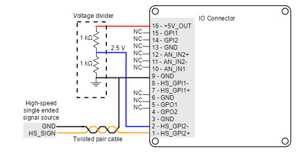
The following figure shows how to connect high-speed single ended signal to HS_GPI2 (same wiring can be used for HS_GPI1).
Jupiter Servo Drive high-speed digital inputs can be used for connecting three-wire sensors. Next figures illustrate the connection of PNP and NPN three-wire sensors in input HS_GPI2 (Same wiring can be used for HS_GPI1). Pin 16 (+5V_OUT) can be used as a supply source.
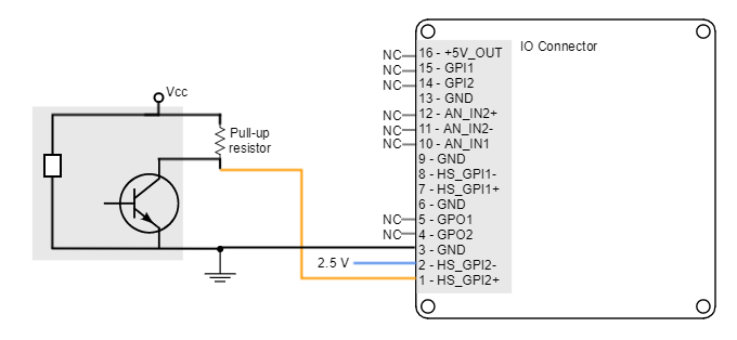
HS_GPI pull-up resistors
Pull-up resistors ensure the desired logic state when the sensor (transistor or relay) is in off-state.
NPN pull-up resistor value must be chosen in order to ensure a positive value in the differential receiver while consuming low current. For a sensor supply of 5 V, 1 kΩ is recommended. For a sensor supply of 24 V, 47 kΩ is recommended.
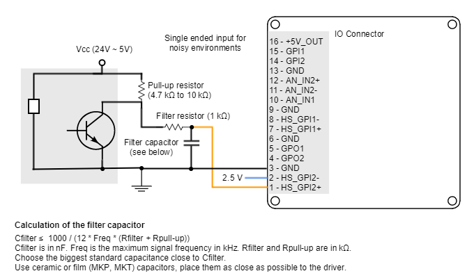
The connection of a NPN three-wire sensor with a noise filter is shown in the next figure.
Analog inputs interface (AN_IN1, AN_IN2)
Jupiter Servo Drive has two 12-bit analog inputs, a single ended one (AN_IN1) and a differential one (AN_IN2). Each one of them has a different input voltage range. Next table summarizes the main features of the analog inputs:
Specification | Analog input 1 | Analog input 2 |
|---|---|---|
Type of inputs | Single ended | Differential |
ESD capability | IEC 61000-4-2 (ESD) ± 15 kV (air), ± 8 kV (contact) | |
Analog input resolution | 12 bits | |
Maximum operating voltage | 0 ~ 5 V | ±10 V |
| Maximum common mode voltage (Analog input 2) | - | ±10 V |
| Maximum voltage on any pin (referred to GND) | 24 V | |
1st order filter cutting frequency (-3 dB) | 5.2 kHz | 5.3 kHz |
| Sampling rate | 10 ksps | |
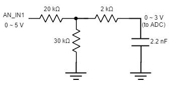
Next figure shows the circuit model for the analog input 1:
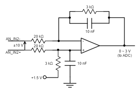
Next figure shows the circuit model for the analog input 2:
Extending AN_IN1 voltage range
To get a 0 ~ 10 V input range in AN_IN1 input, place a 50 kΩ resistor in series with the input.
Non-isolated I/O
Jupiter Inputs and outputs are not isolated. The ground of the Jupiter Servo Drive and the ground of the devices connected to I/Os must be the same. Otherwise inputs or outputs may be damaged.
Next figure illustrates how to connect an analog single ended source to the Jupiter Servo Drive analog input 1.
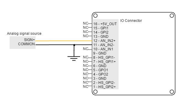
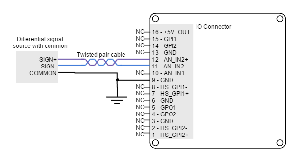
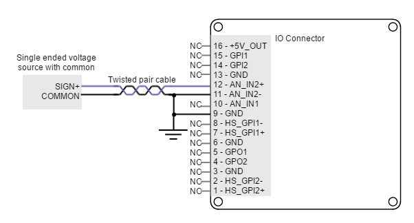
Next figure shows how to interface differential and single ended voltage sources to the differential analog input 2. The differential analog input is typically used as a command source or feedback signal.
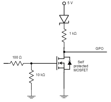
Digital outputs interface (GPO1, GPO2)
Jupiter Servo Drive has two digital non-isolated outputs. Digital outputs are based on an open drain MOSFET with a weak pull-up to 5 V, and are 24 V tolerant and short-circuit protected. Next table shows their main features:
Specification | Value |
|---|---|
Number of outputs | 2 |
Type of output | Open drain output with weak pull-up to 5 V |
ESD capability | IEC 61000-4-2 (ESD) ± 15 kV (air), ± 8 kV (contact) |
Maximum supply output | 30 V (5-24 V typical) |
Maximum sink/source current | Source: low current @ 5 V: 5 mA |
ON-OFF delay | 124 μs @ 30 V and Rload = 100 kΩ |
OFF_ON delay | 15μs @ 30 V and Rload = 100 kΩ |
Max working frequency | 1 kHz |
Next figure shows digital output circuit model.
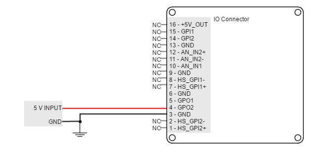
Wiring of 5V outputs
Loads that require 5V as high-level voltage can be connected directly to the digital output. A wiring example for GPO2 is shown in the next figure (same wiring could be used for GPO1).
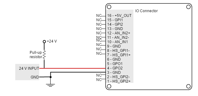
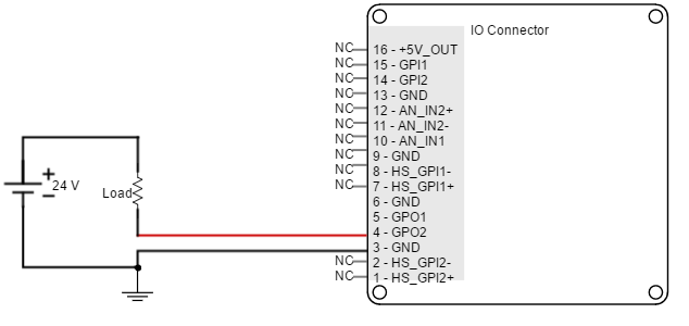
Wiring of 24V outputs
Loads that require 24V as high-level voltage can also be interfaced with GPO. For this option, an external power supply is needed. The load can be connected with a pull-up to 24V or directly switched with the GPO. Next figures show two example connections to GPO2 (same wiring could be used for GPO1).
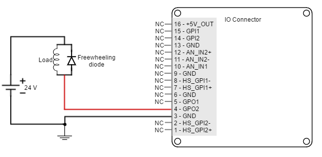
Interfacing inductive loads
The switching of inductive loads (like relays or motor brakes) can cause inductive kicking, that is a sudden voltage rise when the current through the inductor is falls to zero. In order to avoid this voltage rise, it is recommended to place a diode in anti-parallel with the load (known as freewheeling diode).
Standard rectifier diodes such as 1N4002 or 1N4934 are appropriate for the application.
An alternative to the freewheeling diode is to place a varistor or an RC snubber in parallel with the load.
An example of how to connect an inductive load to GPO2 is shown in the next figure (same wiring could be used for GPO1).
Non-isolated I/O
Jupiter Inputs and outputs are not isolated. The ground of the Jupiter Servo Drive and the ground of the devices connected to I/Os must be the same. Otherwise inputs or outputs may be damaged.