Product Description
Denali Safe NET (DEN-S-NET-E) is a Functional Safety certified mid-power, highly integrated, low profile, digital servo drive intended to be plugged or soldered to an application-specific daughter board. The drive includes advanced Functional Safety features, like FSoE (Safety over EtherCAT) communication, Safe Stop and Safe Input as well as best-in-class energy efficiency thanks to its state-of-the-art power stage. The product is based on EtherCAT communication and can be easily configured with the Novanta Drives's free software MotionLab 3 (versions 1.10.0 or above).
Main features:
Ultra-small footprint
Functional Safety: STO, SS1, SS2, SOS, SLS, SLP, SDI, SSR, SV, SP, FSoE; SIL3 and PLe being certified
48 VDC, 5 A continuous
Up to 99% efficiency
Up to 50 kHz current loop, 25 kHz servo loops
20 kHz ~ 200 kHz PWM frequency
16 bit ADC current sensing
Supports Digital Halls, Quadrature Incremental encoder, Absolute BiSS-C encoder
Up to 4 simultaneous feedback sources
Full voltage, current, and temperature protections
Capable of controlling low inductance motors
Target applications:
Collaborative robot joints
Robotic exoskeletons
Medical applications
AGVs and AMRs
Humanoid robot joints
Page contents
Part numbering
Product | Ordering part number | Status | Image |
|---|---|---|---|
Denali Safe NET Functional Safety certified pluggable servo drive with EtherCAT communication. | DEN-S-NET-E | DESIGN COMPLETE | 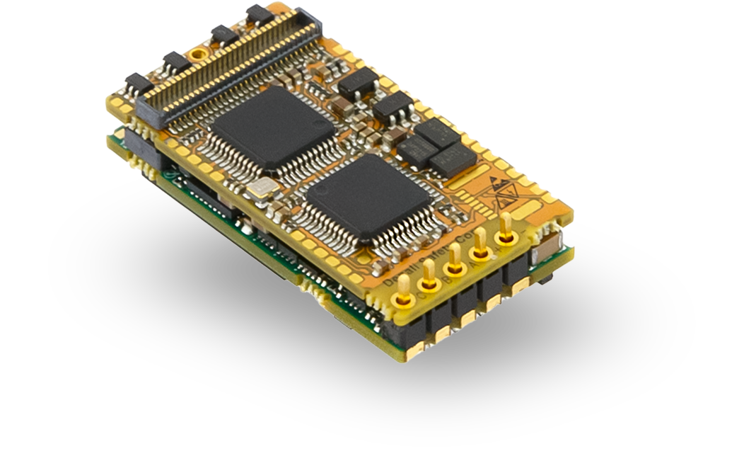 |
General Label Identification |
|---|
Labels Design for DEN-S-NET-E
For Product Revision C (Phase 2):  For Product Revision B (Phase 1):  |
Specifications
Electrical and Power Specifications
Minimum absolute DC bus supply voltage | 8 VDC |
|---|---|
Maximum absolute DC bus supply voltage | 60 VDC |
Recommended power supply voltage range | 8 VDC ~ 48 VDC SELV This voltage range ensures a safety margin including power supply tolerances and regulation during acceleration and braking. |
Internal drive DC bus capacitance | 5 µF ± 30% Note that DEN-S-NET uses ceramic capacitors. The capacitance value varies with DC bias and temperature. |
Logic supply voltages |
During an overvoltage fault, system could become non-operational, but safety function is maintained. |
Boot-up time | 4 s |
Minimum shutdown time | 500 ms |
Output reference voltages | 3.3 V ± 0.2%, 10 mA source / sink capability |
Maximum continuous phase current | 5 A 5 A can be obtained working at 48 V with an appropriate dissipation to keep the product plate under 70 ºC. See Thermal and Power Specifications below and Installation for further details. For disambiguation on current definitions please see Disambiguation on current values and naming for Ingenia Drives. |
Maximum peak phase current | 10 A @ 1 sec Notice that peak current could be limited by an automatic current derating algorithm. |
Maximum continuous output power | > 250 W |
Maximum DC Bus voltage utilization | 99.3% @ 20 kHz These values assume a Sinusoidal commutation and no load connected. |
Minimum Standby Consumption | 1.43 W typ. See details and conditions in Thermal and Power Specifications below |
Motion Control Specifications
Supported motor types | Rotary brushless (SVPWM and Trapezoidal) |
|---|---|
Power stage PWM frequency (configurable) | 20 kHz, 50 kHz (default), 100 kHz, 200 kHz |
Current sensing | 3 phase, shunt-based current sensing. 16-bit ADC resolution. Accuracy is ±2% full scale. |
Current sense resolution | 0.505 mA/counts |
Current sense range | ± 16.5 Apk (full range) |
Max. Current loop frequency (configurable) | 50 kHz Check the Power Stage & Control loops relationship section below. |
Max. servo loops frequency (position, velocity & commutation) (configurable) | 25 kHz Check the Power Stage & Control loops relationship section below. |
Feedbacks |
All feedback inputs are single-ended, 3.3 V logic levels. The following feedback protocols are supported and can be used outside of the Functional Safety certification:
|
Supported target sources | Network communication: EtherCAT with Safety over EtherCAT (FSoE) |
EtherCAT |
Magnetic and capacitive connections supported |
Control modes |
|
Functional Safety Specifications
This product is certification pending. Until receiving the certificate any content in this section is subject to change.
DEN-S-NET-E Safe Motion | |
|---|---|
Safety functions |
|
Safe Feedback | Safe Feedback with the combination of 2 individual encoders:
See the supported Safe Feedback Combinations from below for further details. Safe Encoder are not being supported. |
Safety Integrity Level (SIL) according to IEC 61508:2010 | SIL3 |
Performance Level (PL) according to ISO 13849-1:2015 | PLe, Cat. 3 |
Safety Function Reaction Time | ≤ 25 ms |
Safe inputs | 1 x Redundant Safe Input. Non-Isolated. Logic level (3.3 V and 5 V tolerant). Active-low. |
Command Source |
|
FSoE cycle time | ≤ 50 ms |
Standards compliance | Targeted standards (certification pending):
|
Safe Feedback Combinations
This product is certification pending. Until receiving the certificate any content in this section is subject to change.
Denali Safe NET can provide advanced Safe Motion functions by using two individual non-certified encoders (providing redundancy). It is important to take note that not all feedback combinations are supported for a safe drive (more information can be found below).
They can be integrated either in a system where there is only a motor or a motor and a gearbox attachment. When having a system with a motor + gearbox integration, the feedback sensor of the motor is referred as the redundant feedback and the one connected to the output of the gearbox as the main feedback. When the given system has only a motor, both the main and redundant feedback sensors monitor the same motor shaft.
Feedback Combination | ||
|---|---|---|
Combination code → MotionLab selection | Main feedback sensor | Redundant feedback sensor |
FBC0 → No feedback | - | - |
FBC1 → Primary absolute and secondary absolute | BISS-C BP3 - Port 1 | BISS-C BP3 - Port 2 |
FBC2 → Primary absolute and incremental encoder | BISS-C BP3 - Port 1 | QEI |
FBC3 → Secondary absolute and halls | BISS-C BP3 - Port 2 | Digital Halls |
FBC4 → Incremental encoder and halls | QEI | Digital Halls |
When no feedback sensors are used (FBC0), the available safety functions allowed represent STO, SOUT, SS1 (time monitoring only) and SI.
In the case of using one of the above specified safety feedback combination the allowed safety functions are: STO, SS1, SI, SLS, SSR, SDI, SV, SS2, SS2, SOS, SLP, SLI and SP. For more information about the safety functions check the Safety Manual and the Reference manual.
Note: To guarantee enough diversity, the encoders must be of different technology or manufacturer.
Note: Other feedback combinations can be used for Motion Control purposes out of Functional Safety certification.
Note: Safe Encoders are not supported.
Environmental Conditions
Environmental test methods | IEC 60068-2 |
|---|---|
Case temperature (Operating) | -20 ºC to +70 ºC |
Ambient temperature (Operating) | -20 ºC to +60 ºC |
Case and Ambient temperature (Non-Operating) | -40 ºC to +100 ºC |
Altitude (Operating) | < 2000 m above sea level. |
Vibration (Operating and Non-operating) | 10 Hz to 150 Hz, 1 g |
Mechanical Shock (Operating and Non-operating) | ±5g Half-sine 30 msec |
Pollution degree | Pollution degree 2 with an IP54 enclosure installation. |
Over-voltage category | II |
Maximum Humidity (Operating) | up to 93%, non-condensing at 60 ºC |
Maximum Humidity (Non-operating) | up to 93%, non-condensing at 60 ºC |
Inputs/Outputs and Protections
General purpose Inputs and outputs | 2x non-isolated single-ended digital inputs - 3.3 V logic level. Can be configured as:
2x non-isolated single-ended digital outputs - 3.3 V logic level, 3 mA max. sink / source current. Can be configured as:
2x ±3.3 V ,16-bit, differential analog inputs for load cells or torque sensors. Can be read by the Master to close a torque loop. 1x 0.3 V ~ 3 V, unbuffered analog output. |
|---|---|
Safe Inputs | 1 x Redundant Safe Input. Non-Isolated. Logic level (3.3 V and 5 V tolerant). Active-low. |
Dedicated digital output | Dedicated 3.3 V digital output for Fault Signal status. |
Shunt braking resistor output | Configurable over any of the digital outputs (see above). Enabling this function would require an external transistor or power driver. |
Motor brake output | Dedicated, PWM-capable, 3.3 V digital output for driving a mechanical brake. Turn-on and turn-off times are configurable. Enabling this function would require an external transistor or power driver. |
Motor temperature input | 1x dedicated, 3.3 V, 12-bit, single-ended analog input for measuring motor temperature. NTC, PTC, RTD, linear voltage sensors, silicon-based sensors and thermal switches are supported. |
Protections |
The configurable protections are configurable up to the drive limits. In any case when the limits are reached, the drive is completely switched off with the current reduced to 0.
|
Over-current | An overcurrent device in series (i.e. fuse or similar) is needed with a rating of maximum x3 of the max current of the motor on the system and a minimum voltage rating of 60V Consider Vbus overshoots and reinjections to dimension the protection accordingly. |
Communication for Operation
EtherCAT | CANopen over EtherCAT (CoE) File over EtherCAT (FoE) Ethernet over EtherCAT (EoE) Failsafe over EtherCAT (FSoE) Magnetic and capacitive connections supported |
|---|
Mechanical Specifications
Dimensions | 33 mm x 17.6 mm x 9.5 mm |
|---|---|
Weight | 6.77 g |
Compliance
EC Directives |
|
|---|---|
Electromagnetic Compatibility (EMC) Standards |
|
Product Safety Standards |
|
Functional Safety Standards | See section Functional Safety Specifications |
Environmental Test methods | IEC 60068-2:
|
Thermal and Power Specification
Standby power consumption
The following table shows the standby power consumption when the Everest S Safe power stage is enabled assuming 2 EtherCAT/Ethernet port is active and communicating at full speed, no feedback or I/Os are connected. The standby power consumption calculation for the logic is performed with a 5 V supply. Moreover, the table also shows the "active standby" dc bus power consumption when the power stage is enabled at current mode and a set point of 0 A.
Power supply voltage | Logic supply consumption (5V, 3.3V and Vmagn_ct) | Power stage DC bus consumption switching at 0 current | |||
|---|---|---|---|---|---|
20 kHz | 50 kHz | 100 kHz | 200 kHz | ||
8 V | < 1.5815 W Maximum logic supply consumption The mean logic supply consumption is 1.5250 W | 0.0072 W | 0.0160 W | 0.0320 W | 0.0632 W |
48 V | 0.1296 W | 0.3122 W | 0.6195 W | 1.1249 W | |
60 V | 0.1921 W | 0.4585 W | 0.9003 W | 1.7706 W | |
Measurement environment
No feedbacks connected
No I/Os connected
Motor current is set to 0 (Voltage mode 0 V)
STO circuitry supplied at 3.3 V (consumption considered).
Thermal model
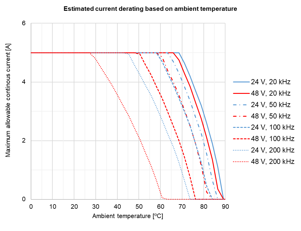
Current derating without plate
The following figure shows the maximum motor phase current at different ambient temperatures and operating points. The graph expresses the achievable current including the derating algorithm that limits the current-based operation conditions and the power stage temperature.
Notice that current is expressed in crest value for a 3-phase BLAC motor, not RMS. For further clarifications and conversion to equivalent RMS values please refer to Disambiguation on current values and naming for Ingenia Drives.
The following considerations apply to this measure:
Drive plugged into a 70 mm x 100 mm interface board.
Power pins are soldered to the board.
Convection dissipation to the air without forced airflow
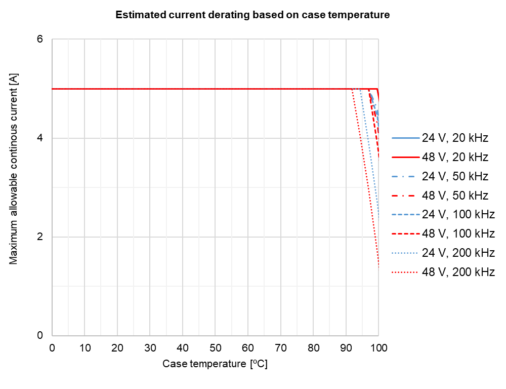
Current derating with case
It is highly recommended to use a case or heatsink to dissipate Denali Safe NET. See the Installation section for further details.
The following figure shows the maximum motor phase current when dissipating the Denali Safe NET with a case or heatsink. Results are referenced to the case temperature, providing a known interface for any system. The graph expresses the achievable current including the derating algorithm that limits the current-based operation conditions and the power stage temperature.
Notice that current is expressed in crest value for a 3-phase BLAC motor, not RMS. For further clarifications and conversion to equivalent RMS values please refer to Disambiguation on current values and naming for Ingenia Drives.
To ensure proper performance of Denali Safe NET, the case temperature should always be held below 85 ºC (Tc-max = 85 ºC).
Heat dissipation and heatsink calculation
The following figure shows the total estimated power losses at different operating points. This includes logic supply which is an important contributor at low loads. As can be seen, lower PWM frequency and voltage lead to lower power losses.
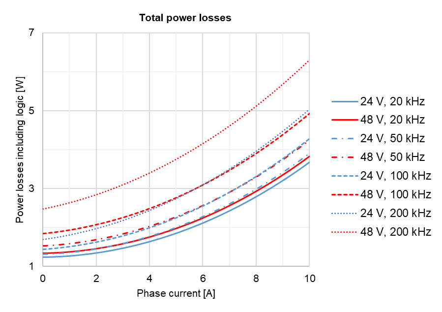
Please, use the following procedure to determine the required heatsink:
Based on the voltage & continuous (averaged) current required by your application and Current derating graph determine the Case temperature Tc. Remember that Case temperature must always be below 85 ºC (Tc < 85 ºC)
For example: If the application requires 4 A @ 48V (100 kHz) the Tc maximum will be 85 ºC
Based on the voltage & continuous current required by your application and the Power losses graph determine the generated Power Losses PL to be dissipated.
For example: If the application requires 4 A @ 48V (100 kHz) the PL will be 2.5 W
Determine the Thermal impedance of the used thermal sheet Rth(c-h)
For example, a thermal sheet TGX-150-150-0.5-0, which has an estimated thermal impedance of Rth(c-h) = 0.2 K/W
Based on the ambient temperature and using the following formula determine the maximum thermal impedance to the air of the required heatsink Rth(h-a)
a. For example: If the application requires 4 A @ 48V (100 kHz) working at Ta = 25 ºC and we use a thermal sheet with Rth(c-h) = 0.2 K/W the required thermal impedance of the heatsink will be Rth(h-a) = 24.2 K/W
Power Stage & Control loops relationship
The power stage PWM frequency can be adjusted in 4 different frequencies. Each frequency has an associated rate for the control loops, as specified in the following table.
Power stage PWM frequency | Current loop frequency | Servo loops frequency (position, velocity, commutation & shunt) |
|---|---|---|
20 kHz | 20 kHz | 20 kHz |
50 kHz | 50 kHz | 25 kHz |
100 kHz | 50 kHz | 25 kHz |
200kHz | 50 kHz | 25 kHz |