Power Supply and Motor Power
Power Supply
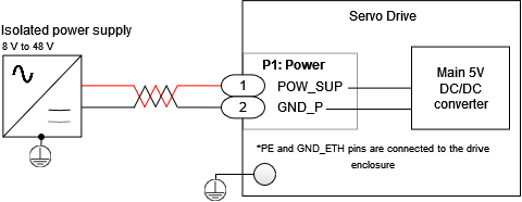
The Servo Drive is powered from a single power supply as shown in the following figure. Providing mechanical fastening can help to avoid ripping the connector (P1) off.
Power Supply Requirements
The choice of a power supply for the Servo Drive is mainly determined by the following criteria:
The power supply must be isolated with a minimum Overvoltage Category of II (Typ ≥ 2500 V isolation). This does not apply if the Drive is battery-powered and isolated from the electrical grid.
The voltage should be targeted for the motor and its speed requirements. See How to dimension a power supply for an Ingenia drive. Ensure it is always within the operating ranges of the Drive specifications. It is strongly recommended to leave a margin between the nominal voltage and the maximum absolute of the drive (60 V) to allow some regenerative braking. Working near the limits can cause faults. By using a ≤50 V power supply all circuits can be considered Safe Extra Low Voltage (SELV) which simplifies installation protection against electric shock.
The current should be the one able to provide the electrical power of the application. The conservative approach is to choose the power supply rated current as your maximum motor current. This conservative approach, however, can lead to oversized power supplies since the DC current is typically lower than the motor current. See Understanding why the motor phase current is different than the power supply current. The power supply current should be determined according to the maximum power point where the product speed · torque is maximum. See more details here How to dimension a power supply for an Ingenia drive. Also, consider the simultaneity factor when having various drives in parallel.
Servo drive systems tend to have large current peaks and regenerate. This can cause overvoltage faults, under-voltage, or even unstabilize the control loop of the power supply. It is preferred to choose robust power supplies with current limiting behavior, overvoltage margin from the nominal, and non-latching fault to prevent shut-down in case of a transient regeneration or overload.
The transformer and rectifier type supplies are simple and reliable. Switch Mode Power Supplies (SMPS) provide good efficiency, low harmonic distortion. Always choose good quality, EMC compliant power supplies.
To determine if the system may have regenerative braking issues check: Dimensioning a Shunt Resistor for Regenerative Braking. See Shunt Braking Resistor Connection next.
Power Supply EMI Filter
In applications that require mitigating conducted and radiated electromagnetic emissions an input EMI filter is necessary. Depending on the application, motor construction, PWM frequency and specific EMC requirements the filter should be chosen. It is possible to share a single EMI filter for various servo drives given that the power ratings are observed.
The connections are shown next, a good PE plane is strongly recommended. Please follow grounding recommendations. Note that the Drive includes a 1 nF 250 V capacitor between GND_P and PE (the drive aluminum enclosure).
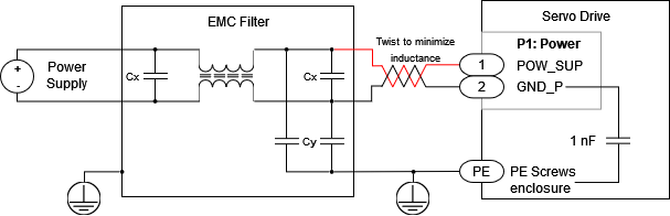
For the lowest EMC, it is recommended to use a 2 stage filter.
Shunt Braking Resistor Connection
A shunt braking resistor can be activated from the Drive by using an external transistor. Any of the 2 general-purpose outputs can be configured to turn-on when the dc bus exceeds a certain threshold: Shunt braking resistor.
The digital outputs provide a 0 ~ 3.3 V output with a 400 Ω in series resistance inside the drive. This will typically be enough to turn on - off a power MOSFET transistor that can withstand the braking current, like IRLR3110ZTRPBF. Ensure that a transient voltage Zener like MM3Z6V2T1G is placed in parallel with the gate of the transistor and a pull-down 10 kΩ resistor ensures a safe off state of the transistor in case of disconnection. If the shunt braking resistor or circuit is inductive a re-circulation diode like V8P10-M3/86A is needed.
Shunt resistor calculation tool
Additional information on shunt braking resistor sizing and a calculation tool can be found here.
Motor Connections
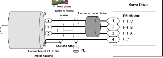
3 Phase Brushless Motor
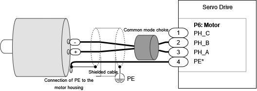
DC Motor
Motor Choke
In applications where electromagnetic compatibility is needed, the use of an external common mode choke is necessary for the motor phases. Please see this document to understand why this is relevant Electromagnetic Interference Issues With Servo Drive Systems.
Note that on applications where the drive is mounted inside the motor or actuator the choke and cable shields may be removed. While the actuator enclosure will provide shielding against radiated EMC, the need or not of common mode choke will depend on motor construction, especially capacitive coupling between windings and housing as well as EMC requirements.
Some choke wiring recommendations are:
Place the choke as close to the drive as possible. The objective is to cancel the noise close to its source (the switching power stage).
Make sure the chosen choke does not saturate at the maximum operating phase current. If this happens, the choke temperature would increase rapidly.
Make only 1 or 2 turns of the motor cables. More than 2 reduces its effectiveness as the capacitive coupling between wires bypasses the choke effect.
PE conductor should never pass through the choke.
Avoid contact of the toroid core with a grounding point.
The next table shows recommended chokes for the Servo Drive.
Type | Manufacturer | Part number | Remarks |
|---|---|---|---|
Wide frequency oval ferrite cable core | Laird Technology | 28B0773-050 | Single turn. Preferred option. |
Wide frequency cylindrical ferrite cable core | Laird Technology | 28B0999-000 | Double turn option. Higher attenuation. |
In case of doing 2 turns, space the phases 120º apart. Start each phase wire in the same rotating direction, wrapping all phases clockwise or anticlockwise. This will add the common-mode flux and increase its impedance.
Power supply and motor cable selection
Power cables for the Drive must be designed according to the averaged RMS current of the application. Check the cable characteristics when selecting the specific cable and please follow the next recommendations:
Use a cable insulator that tolerates ≥ 180 ºC. Silicone or Teflon insulation are suggested. PVC or thermoplastic cables are not recommended due to their low operating temperature.
Use flexible cables to prevent mechanical stress to the soldered pads of the connector.
Power supply
To connect to P1 (Molex 2053410202), the plug housing to be used is Molex 2053380002. The following crimp terminals are recommended by the manufacturer:
Molex 2053425028, accepting wires of 20-22 AWG (0.81 mm - 0.65 mm in diameter).
Molex 2053425128, accepting wires of 24-26 AWG (0.51 mm - 0.40 mm in diameter).
For best electromagnetic compatibility (EMC) the power supply cable inductance should be minimized. Wiring recommendations:
Minimize the area between positive and negative supply voltages. The best practice is by twisting them as can be seen in the wiring diagrams.
Increase cross-section of the cables (Max recommended is 4 mm² CSA, 2.3 mm diameter).
Reduce the distance between the power supply and drive.
Motor
To connect P6 (Molex 2053380004), the plug housing to be used is Molex 2053410204. The following crimp terminals are recommended by the manufacturer:
Molex 2053425028, accepting wires of 20-22 AWG (0.81 mm - 0.65 mm in diameter).
Molex 2053425128, accepting wires of 24-26 AWG (0.51 mm - 0.40 mm in diameter).
Protective earth wire must always have an area equal or superior to the power cables.
Motor and power cables must always be mechanically secured
To prevent damage to the soldered pads of the connectors and ensure a long-term reliable connection it is mandatory to mechanically secure the cables after plugging them.
If you use shielded cables, the EMC clamp can provide this mechanical support.
Mechanical clamps must not have sharp edges that could damage the conductor jacket.