0x2A05 - Brake options
Index | Sub Index | Name | Data Type | Acc. | Pdo Map. | NVM | Value range | Default value | Units |
|---|---|---|---|---|---|---|---|---|---|
0x2A05 | 0x01 | Mode ("available" deprecated from 2.4.9) | UINT8 | RW | No | Yes | UINT8 | 0x00 | - |
0x2A05 | 0x02 | Digital output used (Deprecated) | UINT8 | RW | No | Yes | UINT8 | 0x05 | - |
0x2A05 | 0x02 (0x03 Deprecated) | Delay before release brake | UINT16 | RW | No | Yes | UINT16 | 0 | milliseconds |
0x2A05 | 0x03 (0x04 Deprecated) | Delay after enable brake | UINT16 | RW | No | Yes | UINT16 | 0 | milliseconds |
| 0x2A05 | 0x04 | Duty Cycle | UINT16 | RW | No | Yes | 0 - 2047 (0 - 100%) | 2047 (100%) | % of brake released |
| 0x2A05 | 0x05 | Full release brake pulse time | UINT16 | RW | No | Yes | UINT16 | 0 | milliseconds |
This object allows configuring the external mechanical brake. If brake is present it is automatically controlled and activated/deactivated by the system depending on the state (See State machine for further information).
This register is fully available from the EMCL version 1.3.0. Older versions have this object structure:
- 0x2A05 0x01 - Available
- 0x2A05 0x02 - Digital output used
- 0x2A05 0x03 - Delay before release brake
- 0x2A05 0x04 - Delay after enable brake
Brake Mode
The brake can be operated in two different ways, named as automatic and manual modes. By writing a value of 1 to the "Mode" subindex, the drive configures the brake to work in automatic mode, this means that the drive will control the brake, activating or deactivating it when is necessary. By writing a value of 0 to this subindex, the drives starts the manual brake operation mode, so the brake must be externally operated by using 0x60FE - Digital outputs register.
For motors without brake, Manual Brake mode can be used, so let this subindex with default value.
Summarizing:
| Subindex | Value | Operation Mode |
|---|---|---|
| 0x01 | 0 | Manual Brake mode |
| 0x01 | 1 | Automatic Brake mode |
Remember that in manual brake mode the drive will never activate the brake neither in emergency situations, it should be manually activated.
Digital output
The digital output used as brake is configurable using the 0x2A11 - GPO mapping parameter register.
The polarity of the brake (active high or active low) can be configured using the 0x2A02 - Digital inputs/outputs polarity register.
For older EMCL versions (before version 1.3.0), the digital output used can be selected directly from this object.
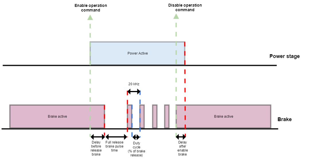
Delay before/after release brake (only in Automatic mode)
The delay between activation/deactivation of the power stage and deactivation/activation of the brake could be also configured.
The brake can be modulated using the duty cycle subindex.
PWM
When the driver enters in operation enable, a full release brake (100% duty cycle) can be applied during the specified milliseconds in the subindex. For manual mode, the specified Duty cycle will be applied always, so it must be modified manually in order to variate from full brake release (DC 100%) to modulated brake (i.e. DC 50%).
The PWM frequency is 20kHz.
The following drawing shows the different parameters in a typical transition between Switched on and Operation enabled status.
The GPO modulation is hardware dependent. Please refer to the drive installation manual for further information.