Power Supply and Motor Power
Single Power Supply
The Everest XCR can be powered from a single power supply as shown in the following figure. Since the power cables are soldered to the board it is essential to provide mechanical fastening to avoid ripping them off.
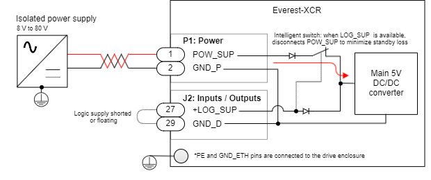
Power Supply Requirements
The choice of a power supply for Everest is mainly determined by the following criteria:
- The power supply must be isolated with a minimum Overvoltage Category of II (Typ ≥ 2500 V isolation). This does not apply if Everest is battery-powered and isolated from the electrical grid.
- The voltage should be targeted for the motor and its speed requirements. Ensure it is always within the operating ranges of the Everest specifications. It is strongly recommended to leave a margin between the nominal voltage and the maximum absolute of the drive (80 V) to allow some regenerative braking. Working near the limits can cause faults. Note that for safety-critical applications a ≤50 V power supply has the advantage that all circuits can be considered Safe Extra Low Voltage (SELV) which simplifies installation protection against electric shock.
- The current should be the one able to provide the electrical power of the application. The conservative approach is to choose the power supply rated current as your maximum motor current. This conservative approach, however, can lead to oversized power supplies since the DC current is typically lower than the motor current. See Understanding why the motor phase current is different than the power supply current. The power supply current should be determined according to the maximum power point where the product speed · torque is maximum. Also, consider the simultaneity factor when having various drives in parallel.
- Servo drive systems tend to have large current peaks and regenerate. This can cause overvoltage faults, under-voltage, or even unstabilize the control loop of the power supply. It is preferred to choose robust power supplies with current limiting behavior, overvoltage margin from the nominal, and non-latching fault to prevent shut-down in case of a transient regeneration or overload.
The transformer and rectifier type supplies are simple and reliable. Switch Mode Power Supplies (SMPS) provide good efficiency, low harmonic distortion. Always choose good quality, EMC compliant power supplies.
To determine if the system may have regenerative braking issues check: Dimensioning a Shunt Resistor for Regenerative Braking. See Shunt wiring next.
Dual Power Supply
For systems where it is necessary to keep communications alive, or keeping position information with incremental sensors while power is off, the drive can be powered from a logic supply input on the I/O connector. Choose the main power supply as indicated above. There are no special power supply sequencing requirements.
![]() Powering the logic supply at a lower voltage than the power will reduce the standby loss by increasing the efficiency of the main DC/DC converter.
Powering the logic supply at a lower voltage than the power will reduce the standby loss by increasing the efficiency of the main DC/DC converter.
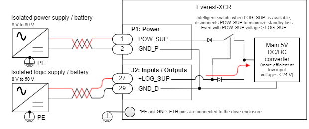
Note GND_P and GND_D are internally connected in the drive. It is not needed or recommended to duplicate this connection externally.
Logic Supply Requirements
The logic supply should meet the following criteria:
- The logic supply must be isolated with a minimum Overvoltage Category of II (Typ ≥ 2500 V isolation) or battery powered.
- The recommended voltage is range is 8 V to 26.4 V (SELV/PELV). The maximum voltage is 50 V. Lower voltages reduce standby losses by making the DC/DC converter on a low loss point.
- The power of the logic should be at least 5 W.
Power Supply EMI Filter
In applications that require mitigating conducted and radiated electromagnetic emissions an input EMI filter is necessary. Depending on the application, motor construction, PWM frequency and specific EMC requirements the filter should be chosen. It is possible to share a single EMI filter for various servo drives given that the power ratings are observed.
The connections are shown next, a good PE plane is strongly recommended. Please follow grounding recommendations. Note that the Everest XCR includes 2 x 1 nF 2 kV capacitors between GND_P and PE (the drive aluminum enclosure).
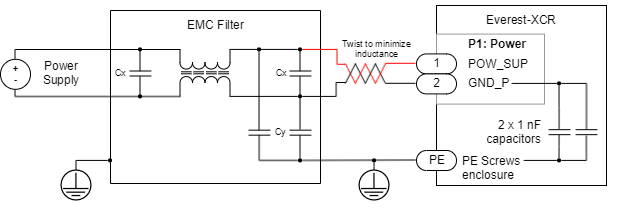
For the lowest EMC, it is recommended to use a 2 stage filter like TE Connectivity 30EMC6.
Shunt Braking Resistor Connection
A shunt braking resistor can be activated from Everest XCR by using an external transistor. Any of the 4 general-purpose outputs can be configured to turn-on when the dc bus exceeds a certain threshold: Shunt braking resistor.
The digital outputs provide a 0 ~ 5 V output with a 470 Ω in series resistance inside the drive. This will typically be enough to turn on - off a power MOSFET transistor that can withstand at least 30 A braking current, like IRLR3110ZTRPBF. Ensure that a transient voltage Zener like MM3Z6V2T1G is placed in parallel with the gate of the transistor and a pull-down 10 kΩ resistor ensures a safe off state of the transistor in case of disconnection. If the shunt braking resistor or circuit is inductive a re-circulation diode like V8P10-M3/86A is needed.
![]()
Shunt resistor calculation tool
Additional information on shunt braking resistor sizing and a calculation tool can be found here.
Motor Connections
3 Phase Brushless
DC Motor
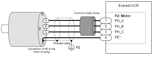
Motor Choke
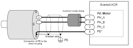
In applications where electromagnetic compatibility is needed, the use of an external common mode choke is necessary for the motor phases. Please see this document to understand why this is relevant Electromagnetic Interference Issues With Servo Drive Systems.
Note that on applications where the drive is mounted inside the motor or actuator the choke and cable shields may be removed. While the actuator enclosure will provide shielding against radiated EMC, the need or not of common mode choke will depend on motor construction, especially capacitive coupling between windings and housing as well as EMC requirements.
Some choke wiring recommendations are:
- Place the choke as close to the drive as possible. The objective is to cancel the noise close to its source (the switching power stage).
- Make sure the chosen choke does not saturate at the maximum operating phase current. If this happens, the choke temperature would increase rapidly.
- Make only 1 or 2 turns of the motor cables. More than 2 reduces its effectiveness as the capacitive coupling between wires bypasses the choke effect.
- PE conductor should never pass through the choke.
- Avoid contact of the toroid core with a grounding point.
The next table shows recommended chokes for the Everest XCR.
Type | Manufacturer | Part number | Remarks |
|---|---|---|---|
| Wide frequency oval ferrite cable core | Laird Technology | 28B0773-050 | Single turn. Preferred option. |
| Wide frequency cylindrical ferrite cable core | Laird Technology | 28B0999-000 | Double turn option. Higher attenuation. |
In case of doing 2 turns, space the phases 120º apart. Start each phase wire in the same rotating direction, wrapping all phases clockwise or anticlockwise. This will add the common-mode flux and increase its impedance.
Power Wiring Recommendations
Cable Selection
Power cables for the Everest XCR must be designed according to the averaged RMS current of the application. Please follow the next recommendations:
- The cable insulator must tolerate ≥ 180 ºC. Silicone or Teflon insulation are suggested. PVC or thermoplastic cables are not recommended due to their low operating temperature.
- Use flexible cables to prevent mechanical stress to the solder joints.
- For an easy and comfortable integration, the diameter of the conductor should not exceed 2.4 mm, the solder pad has a 2.6 mm in diameter.
The following are recommended wire gauges. The minimum gauge is based on a self-heating to 180 ºC of a Silicone or Teflon cable. Note that this may not be acceptable in applications that cannot tolerate this cable temperature.
| Operating RMS current | Conductor diameter (mm) | Minimum Cross-Sectional Area (CSA mm²) | Minimum wire gauge | Conductor diameter (mm) | Recommended Cross-Sectional Area (CSA mm²) | Recommended wire gauge |
|---|---|---|---|---|---|---|
| 45 ARMS | 2.6 mm | 5.3 mm² | 10 AWG | 3.3 mm | 8.4 mm² | 8 AWG |
| 30 ARMS | 1.3 mm | 1.3 mm² | 16 AWG | 2.1 mm | 3.3 mm² | 12 AWG |
| 18 ARMS | 1.0 mm | 0.8 mm² | 18 AWG | 1.3 mm | 1.3 mm² | 16 AWG |
| 12 ARMS | 0.8 mm | 0.5 mm² | 20 AWG | 1.0 mm | 0.8 mm² | 18 AWG |
Protective earth wire must always have an area equal or superior to the power cables and always no less than 2.5 mm² (13 AWG).
For best electromagnetic compatibility (EMC) the power supply cable inductance should be minimized. Wiring recommendations:
- Minimize the area between positive and negative supply voltages. The best practice is by twisting them as can be seen in the wiring diagrams.
- Increase cross-section of the cables (Max recommended is 8.4 mm² CSA, 3.3 mm diameter).
- Reduce the distance between the power supply and drive.
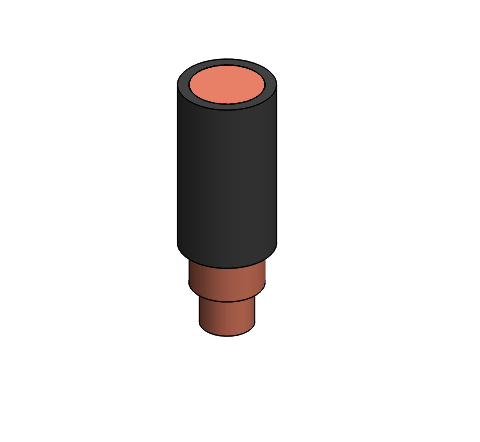
Using 10 AWG ~ 8 AWG wires recommendations
To reach maximum current capability, 10 - 8 AWG wires must be used. In that case, the conductor diameter will be wider than the solder pad. 2 soldering options are recommended for best thermal and mechanical performance:
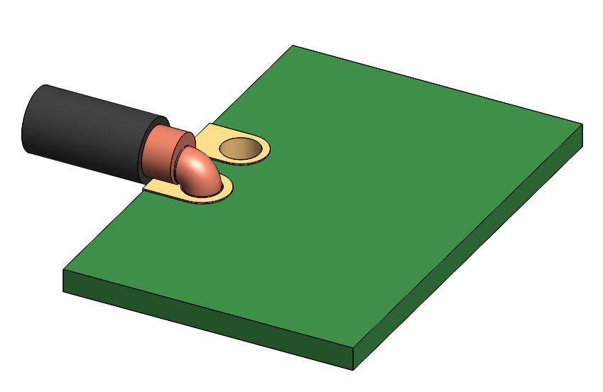
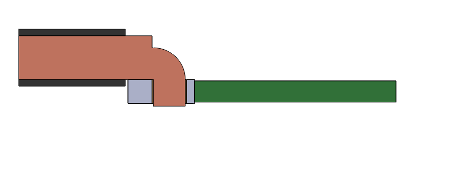
Option 1: Vertical entry
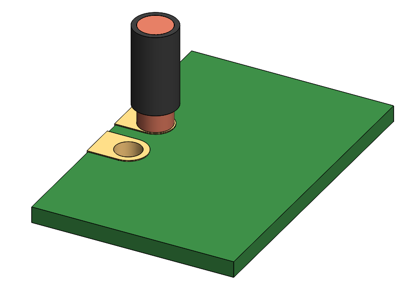
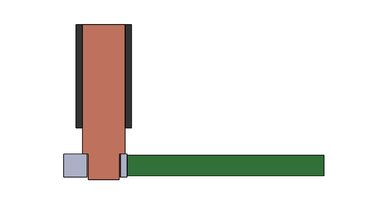
Option 2: Lateral entry
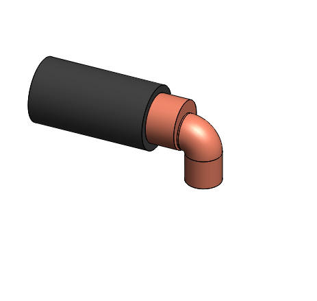
Soldering Power Pins
The power wires of the Everest-XCR should be soldered appropriately to ensure a reliable and low resistance connection. The solder holes are 2.6 mm in diameter. ensure the cable diameter does not exceed this. Always use RoHS compliant solder tin.
Please follow these steps:
- Cut and peel the power cables in advance with the appropriate length. The peeled length can be around 3 mm. Do not cut them after soldering as it will cause permanent tensions.
- Pre-tin the stranded wires by applying the solder with flux to the wire using a heated soldering iron tip. This can be done with a solder bath method. Ensure a minimum solder time of 2 ~ 3 seconds.
- Solder shall penetrate the inner strands of stranded wire.
Solder shall not obscure the wire contour at the termination end of the insulation.
Anti‐wicking tools are strongly recommended in order to protect the cable insulation.
- Apply flux to the pads with a brush to ensure surfaces are clean and there is sufficient flux.
- Pre-tin the solder pads of the Everest-XCR using Rohs-free solder. Take precautions with the solder balls not to create any short. Do not fill the hole.
- Position the wire inside the hole with the desired cable exit direction and solder them with a clean solder tip. Additional solder may be needed.
- Clean the flux residues with appropriate solvents like isopropyl alcohol (IPA).
- Do not cut the wires after soldering as it may cause permanent stress and long term reliability issues.
Further tips on best practices can be found in ESA standard ECSS-Q-ST-70-08C.
Danger!
Power and motor pins have live voltages in excess of 50 V which can cause electric shock! It is essential to perform connection or commissioning procedures without power.
Les broches de l'alimentation et du moteur ont une tension supérieure à 50 V qui peut provoquer un choc électrique ! Il est essentiel d'effectuer les procédures de connexion ou de mise en service sans alimentation électrique.
Motor and power cables must always be mechanically secured
To prevent damage to the solder joint and ensure a long-term reliable connection it is mandatory to mechanically secure the cables after soldering.
If you use shielded cables, the EMC clamp can provide this mechanical support.
Mechanical clamps must not have sharp edges that could damage the conductor jacket.