Product Description
Jupiter is a high performance closed loop servo drive controller suitable for DC brushed, voice coils and brushless motors.
Its incredibly compact design includes multiple communication ports, enabling thus a wide choice of interfacing methods. Its extended voltage operating range allows its use in several applications, and the small footprint and the needless of an external heatsink allow the controller to be a valid OEM for critical-size applications.
The Jupiter Digital Servo Drive has been designed with efficiency in mind. It incorporates cutting-edge MOSFET technology as well as optimized control algorithms to provide the perfect trade-off between EMIs and efficiency.
Jupiter Servo Drive is provided with several general purpose inputs and outputs designed for 5V TTL logic but tolerant up to 24V and fully rugged. By using these inputs and outputs it is possible to implement alarm signals, connect digital sensors, activate external devices (LEDs, actuators, solenoids, etc.). Some of the digital and analog inputs can also be used as command / target sources.
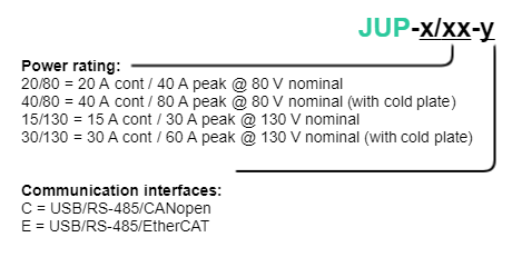
Jupiter part numbering
Ordering part number | Status | Image |
|---|---|---|
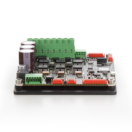
JUP-40/80-C | PRODUCTION |
|
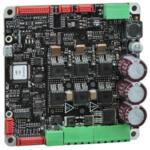
JUP-30/130-C | OBSOLETE | |
JUP-20/80-C-P | ON DEMAND |
|
JUP-15/130-C-P | OBSOLETE | |
JUP-40/80-E | OBSOLETE | - |
JUP-30/130-E | OBSOLETE | |
JUP-20/80-E-P | OBSOLETE | - |
JUP-15/130-E-P | OBSOLETE |
Specifications
Electrical and power specifications | ||||
|---|---|---|---|---|
| Part number → | JUP-20/80-y-P | JUP-40/80-y | JUP-15/130-y-P | JUP-30/130-y |
Nominal power supply voltage | 10 VDC to 80 VDC | 10 VDC to 130 VDC | ||
| Maximum absolute continuous power supply voltage | 85 VDC | 135 VDC | ||
| Transient peak voltage | 95 V @ 100 ms | 145 V @ 100 ms | ||
| Logic supply voltage | 10 VDC to 90 VDC If logic supply is not connected, the board is powered from power supply with a bypass diode | 10 VDC to 90 VDC Two different supplies are needed for this version. Note that logic supply voltage < power supply voltage. Do not connect them together at voltages > 95 V ! | ||
| Logic supply power | 5 W (considering I/O and feedback supplies) | |||
| Internal DC bus capacitance | 600 µF | 450 µF | ||
| Minimum motor inductance | 300 µH | |||
Nominal phase continuous current | 20 ARMS | 40 ARMS | 15 ARMS | 30 ARMS |
Maximum phase peak current | 40 ARMS (5 s) | 80 ARMS (5 s) | 30 ARMS (5 s) | 60 ARMS (5 s) |
| Current sense range | ± 75 A | ± 110 A | ± 75 A | ± 110 A |
| Current sense resolution | 146.48 mA/count | 213.85 mA/count | 146.48 mA/count | 213.85 mA/count |
| Shunt braking transistor | Shunt braking transistor on board. 40 A maximum current. Product Description | |||
| Cold plate | Yes | Yes | Yes | Yes |
| Power stage | Same power semiconductors for both references. The cold plate allows better heat dissipation and therefore greater current rating. | Same power semiconductors for both references. Power stage in 130 V part numbers is less efficient than the one in 80 V part number. This explains the reduced current range of high voltage references. | ||
| Power connectors | Pluggable terminal 5 mm pitch | Screw terminal 6.35 mm pitch | Pluggable terminal 5 mm pitch | Screw terminal 6.35 mm pitch |
Standby power consumption | 1.5 W (max) | |||
Efficiency | > 97% at the rated power and current | |||
Motion control specifications | ||||
| Motion control core | Ingenia E-Core with EMCL2. | |||
Supported motor types |
| |||
Power stage PWM frequency | 20 kHz (default) 40 kHz (alternative PWM frequency, configurable) | |||
| Current sensing | On phases A, B and C using 3 terminal shunt resistors. Accuracy is ± 1% full scale. 10 bit ADC resolution. | |||
Sensors for commutation (brushless motors) |
It is recommended to install the SSI only firmware variant if absolute encoder SSI is used for commutation. | |||
| Sensors supported for servo loops |
| |||
Supported target sources |
| |||
Inputs/outputs and protections | ||||
| Inputs and outputs |
| |||
Protections |
| |||
| Safe Torque Off (STO) | Fully functional STO inputs. 2 x 4.5 V to 24 V tolerant isolated inputs. | |||
| Motor brake | Dedicated motor brake output. Up to 130 V and 1 A. PWM operation and integrated freewheeling diode. | |||
Communications | ||||
| USB | µUSB (2.0) connector. The board can be supplied from USB for configuration purposes but will not power the motor. | |||
| Serial | RS485 full-duplex (compatible with RS422), isolated (> 2.5 kV). Includes jumper to enable 120 Ω termination. | |||
| CANopen | Available. Isolated (> 2.5 kV). Includes jumper to enable 120 Ω termination. CiA-301, CiA-305 and CiA-402 compliant | |||
| EtherCAT | Available. | |||
Environmental and mechanical specifications | ||||
Ambient air temperature |
| |||
Maximum humidity | 5% - 85% (non-condensing) | |||
120 mm x 101 mm x 28.1 mm (with plate) | 120 mm x 101 mm x 28.1 mm (with plate) | 120 mm x 101 mm x 28.1 mm (with plate) | 120 mm x 102 mm x 30.1 mm (with plate) | |
Weight (exc. mating connectors) | 258 g | 258 g | 258 g | 263 g |
| MTBF | On demand | > 450.000 h Based on FIDES method for Standard Life Profile at 40 °C average. Other scenarios available on demand. | On demand | On demand |
Hardware revisions
| Hardware revision* | Description and changes |
|---|---|
1.0.1B May 2015 | First product demo. |
1.1.0R September 2015 | First product release. Changes from previous version:
|
2.0.0 December 2016 | Second Jupiter release.
|
2.2.0 February 2021 | Changed PCB finish to gold plating. |
Identifying the hardware revision
Hardware revision is screen printed on the board.
Power and current ratings
To achieve Jupiter current ratings it is necessary to provide sufficient heat dissipation. For the JUP-20/80-x and JUP-15/130-x versions (that do not include an aluminium cooling plate), convection cooling is typically enough to provide nominal current from up to 50ºC ambient air temperature. From 50ºC to 100ºC of ambient temperature a current derating is needed.
For the high current versions JUP-40/80-x and JUP-30/130-x, that are supplied with aluminum plate or cold plate, additional cooling (apart from natural air convection) is necessary to achieve its nominal ratings. This means screwing the plate to a cooling surface, such as a heatsink, cooling plate or most typically a metallic structure of the machine or motor.
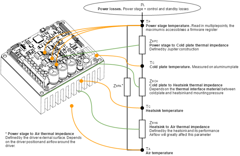
Excessive power losses lead to over temperature that will be detected and cause a the drive to turn off. The system temperature is available in E-Core registers and is measured near the power stage. The temperature parameter that can be accessed from USB 2.0, CAN or serial interfaces does not indicate the air temperature. Above 110ºC the Jupiter automatically turns off the power stage and stay in fault state avoiding any damage to the drive. A Fault LED will be activated and cannot be reseted unless temperature decreases.
To determine whether it is necessary to use an additional heatsink, and the current ratings that are achievable, please see the following points.
Drive safety is always ensured by its protections. However, power losses and temperature limit the allowable motor current.
Some parts of the Jupiter exceed 110ºC when operating, especially at high load levels.
Do not touch the Jupiter when operating and wait at least 5 minutes after turn off to allow a safe cool down.
Following figure shows the basic power flow and losses in a servo drive system.
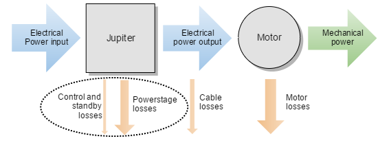
Power losses calculation (heat dissipation)
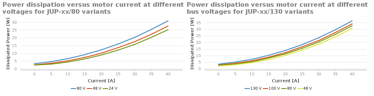
Operation of the Jupiter causes power losses that should be transferred to the surrounding environment as heat. Heat dissipation depends on various parameters. Principally:
- Motor RMS current: positive correlation.
- DC bus voltage: positive correlation.
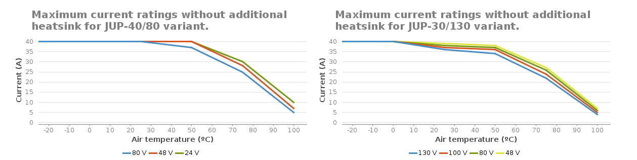
- Jupiter product number: 130 V variants JUP-15/130 and JUP-30/130 have different power transistors compared to the 80 V variants. The 130 V variants have greater power losses for a given motor current. Different charts are provided for each variant, see below.
Other less relevant parameters affect also the power loss but are not considered in the graphs:
- Air temperature, higher power semiconductor temperatures reduce their efficiency.
- Motor speed. Faster motor speeds result in higher overall power loss since the input current is greater. This increases conduction losses on the reverse polarity protection circuitry.


Current ratings (without cold plate)
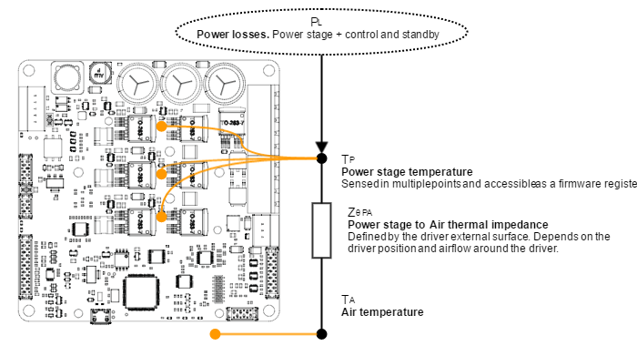
In the Jupiter Servo Drive without cold plate, the board itself is the heatsink. Power losses cause the drive to increase its temperature according to:
Power losses have a positive correlation with the motor RMS current. For this reason, when the ambient temperature rises, the output current must be limited to avoid an excessive drive temperature (TP< 110ºC). The threshold temperature where the current derating should start depends on the DC bus voltage and the Jupiter part number.
The thermal impedance typical value is shown below, however its exact value will vary according to:
- Air flow around the drive.
- Position (vertical allows natural convection).
| Parameter | Value | Units | Notes | |
|---|---|---|---|---|
| Maximum over-temperature fault | 110 | ºC | Measured on the power stage (not the heatsink) and accessible via register | |
| Thermal resistance from power stage to air | no cold plate | 4.6 | ºK/W | Variants 20/80, 15/130 (this variants do not include cold plate) |
| with cold plate | 2.1 | ºK/W | Variants 40/80, 30/130 (this variants include cold plate) | |
| Maximum power dissipation without heatsink | no cold plate | 13.3 | W | At TA 50ºC |
| with cold plate | 28.6 | W | ||
| Thermal resistance from power stage to heatsink (cold plate version) | 1.2 | ºK/W | Thermal resistance between cold plate and heatsink not considered | |
| Thermal time constant | no cold plate | 600 | s | Temperature stabilization is found after ~ 3 τ |
| with cold plate | 3700 | s | ||
Typically, the Jupiter without cold plate is suitable when power dissipation is < 13.3 W. This indicates that the maximum current it can withstand at 50 ºC is 20 A at 80 V bus voltage.
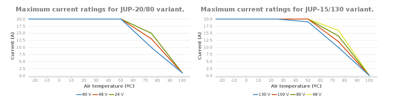


Current derating
The current derating graph is only indicative and is based on thermal tests performed in a climatic room where there was enough room for natural air convection. Each application may reach different ratings depending on the installation, ventilation or housing. Current derating is only a recommendation and is not performed automatically by the drive.
Dynamic application (non-constant current)
The Jupiter has a great thermal inertia that allows storing heat during short power pulses (exceeding nominal current) without overpassing the maximum temperature. This allows achieving high peak current ratings without need of additional heatsink.
For most systems where the cycle time is shorter than 3 τ (thermal time constant) the equivalent current can be calculated as the quadratic mean of the current during the full cycle. The load cycle can be simplified as different constant currents during some times:
Where:
T is the full cycle period.
I1 is the current during t1
I2 is the current during t2
In is the current during tn
System temperature
Next thermal image shows an example of the heat distribution in a JUP-20/80-y. This test has been performed without cold plate at maximum load and air temperature in a 3 phase application.

The drive is getting hot even at 0 current!
This is normal. Jupiter power stage includes high power MOSFET transistors which have parasitic capacitances. Switching them fast means charging and discharging those capacitors thousands of times per second which results in power losses and temperature increase even at 0 current!
Recommendation: when motor is off, exit motor enable mode which will switch off the power stage.
Improving heat dissipation with a heatsink (Jupiter with cold plate)
In Jupiter variants with cold plate, a heatsink may be needed to extend the current range at high temperatures. As a general rule, if the power dissipation is < 28.6 W, no heatsink is needed. When using high efficiency heatsinks or in enclosed spaces the equation can be simplified as follows.


Assembly recommendations for best heat dissipation
- Always allow natural air convection by ensuring ≥ 10 mm air space around the drive.
- Place the Jupiter in vertical position.
- Use a good thermal interface material to improve the heat dissipation when using heatsink. See Product Description for details.
- If housed, use a good thermal conductivity material such as black anodized aluminum. Placing the drive in a small plastic package will definitively reduce its temperature range.
- Temperature range can be increased by providing forced cooling with a fan or by placing a thermal gap pad on top of the board. Always ensure electrical isolation between live parts and the heatsink.
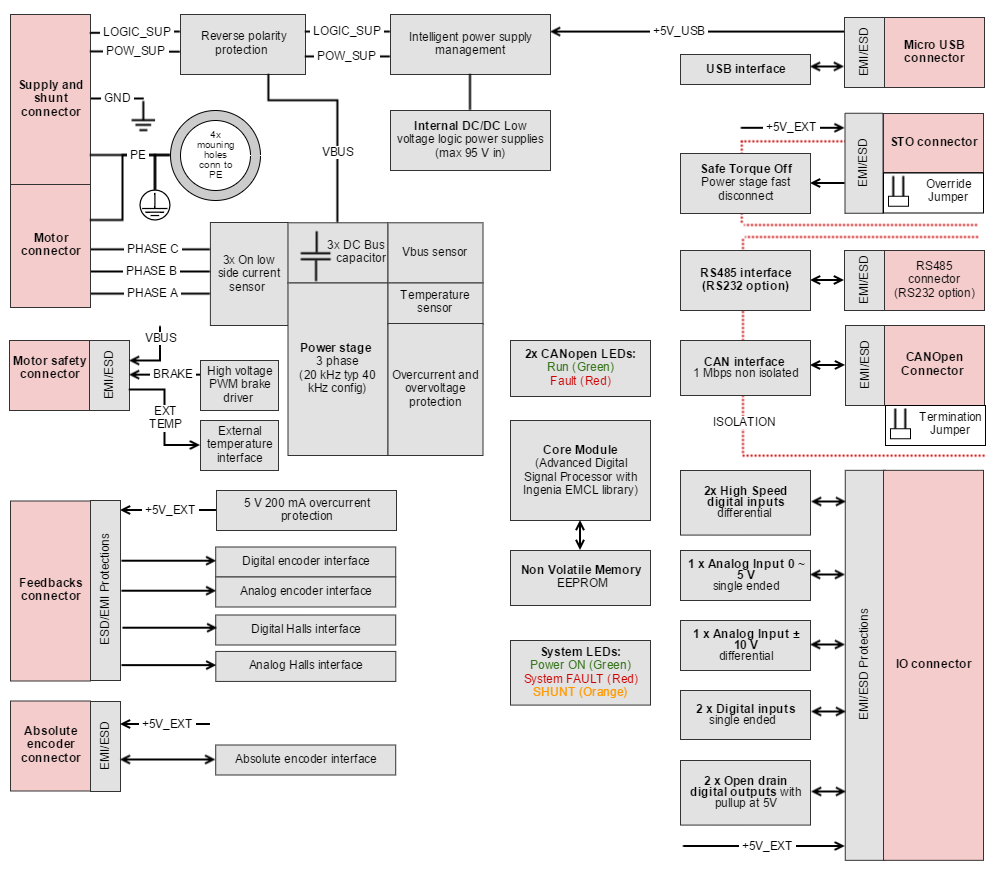
Architecture